
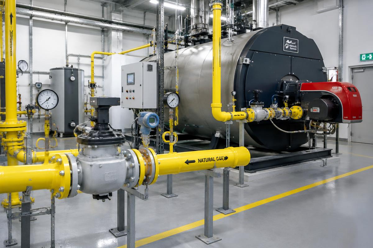
An industrial natural gas installation is not just a pipe carrying fuel to a burner. It is a comprehensive system of supply, regulation, metering, and safety. To properly diagnose a fault or perform a correct operational check, one must first understand the gas flow path and the role of each component.
The basic path of natural gas
In a typical industrial installation, the gas is received from the grid, passes through the metering point, and, where required, through a pressure reduction or regulation stage. It is then distributed through the facility's main network to individual consumers, such as boilers, furnaces, dryers, or production lines.
Each consumer has its own local isolation and safety setup. For burners, this arrangement typically includes a filter, a regulator or stabilizer where applicable, a pressostat, safety valves, and the instruments required by the manufacturer.
Main network and branch lines
The main network must be capable of meeting the total demand of the installation without an unacceptable pressure drop. Individual branches supply different machines and may have different flow and pressure requirements.
In an installation with many large burners, the operation of one consumer can affect the others. That is why we never examine a pressure problem in isolation within the gas train alone. We also check what is happening in the main network.
Isolation points
Manual valves allow for the isolation of sections for maintenance or in case of emergency. They must be accessible, identifiable, and part of a clear safe isolation procedure.
Safety systems
The safety of an industrial installation relies on more than one layer of protection. For instance, there may be a central shut-off solenoid valve, gas detectors, emergency stops, pressostats, combustion air monitoring, flame control, and valve proving.
The important aspect is that these devices work together. A trip at one point may cut off supply to an entire line or just to one consumer, depending on the logic of the installation.
Why the installation diagram is important
An updated piping and instrumentation diagram (P&ID) helps us know where to measure pressure, which valve isolates which section, and which safety device affects each consumer. Without this overview, diagnosis is often done through trial and error rather than methodical checking.
Conclusion
A proper understanding of an industrial installation begins with its overall architecture. From supply to burner, every element has a specific role in flow, pressure, metering, and safety. Interventions on natural gas networks must be carried out by qualified personnel and in accordance with the design, manufacturer instructions, and applicable safety requirements.