
What is earthing resistance and why is it measured
Earthing is a fundamental part of protecting an electrical installation against electric shock. Through protective conductors and the main earthing terminal, it connects the exposed metal parts of devices to the installation's protection system. In the event of insulation failure, protection depends on the correct cooperation between the earthing, conductors, equipotential bonding, and automatic disconnection devices.
Earthing resistance is expressed in Ω and describes the resistance between the electrode (or electrode system) and remote earth. It is influenced by the material and geometry of the electrodes, the quality of connections, and, most importantly, the soil resistivity. Moisture, composition, and soil temperature can significantly alter the result.
Earthing resistance measurement is not the same as measuring the continuity of the protective conductor or testing an RCD. A low reading on an earth tester does not prove that every socket and device is properly protected. Comprehensive assessment requires additional electrical tests.
How earthing resistance is measured
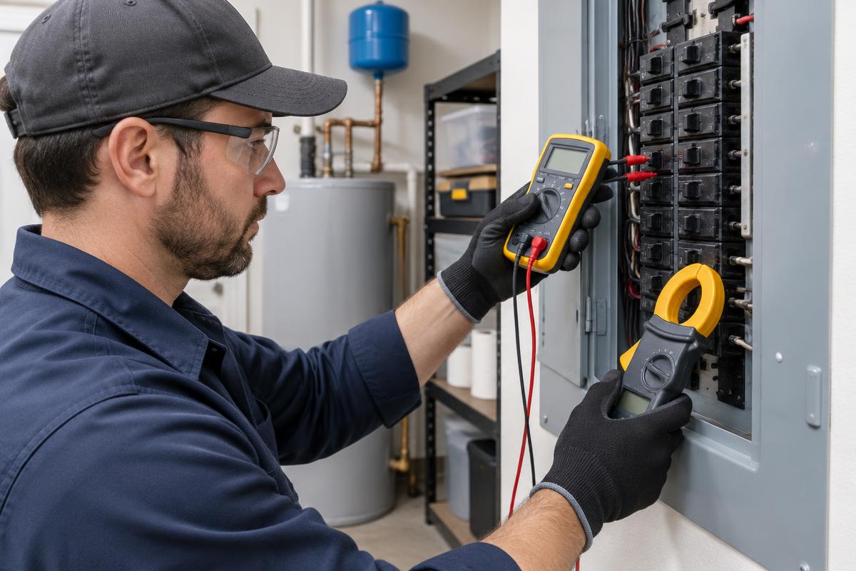
The test is performed by a licensed electrician using an appropriate earth tester or an electrical installation testing device that supports the specific method. A simple multimeter cannot replace this measurement. Before selecting a method, the earthing system, the layout of the electrodes, and any parallel conductive paths are identified.
- Fall-of-potential method: uses the electrode under test and auxiliary electrodes in the ground. The device injects a test current and measures the potential difference, from which it calculates the resistance. Adequate distance and correct electrode placement are critical.
- Measurement with an earth clamp meter: is suitable when there is a closed loop through multiple earthing connections. It measures the loop resistance and does not independently evaluate an individual electrode without a return path.
- Selective measurement: combines auxiliary electrodes and a suitable clamp meter to isolate the contribution of a specific branch, provided the instrument and the installation allow it.
In the fall-of-potential method, reliability is checked by moving the potential electrode and comparing the readings. The well-known 62% rule is only applied under specific conditions of geometry, distance, and soil, not as a universal recipe.
If disconnection of the earthing conductor is required, it must be performed exclusively within a safe procedure by the electrician, with isolation of the installation where necessary. Never disconnect the earth for testing on a live installation.
What earthing resistance value is safe?
There is no single value in Ω that characterizes every electrical installation as safe. Acceptance depends on the earthing system, protective devices, required disconnection times, and applicable requirements. Limits such as "under 10 Ω" or "under 1 Ω", without further context, do not constitute a general electrical safety rule.
In a TT system with protection via a Residual Current Device (RCD), the condition RA × IΔn ≤ UL is used. RA includes the resistance of the electrode and the associated protective conductor, IΔn is the rated residual operating current, and UL is the conventional touch voltage limit. In standard AC conditions, 50 V is used, while special applications may require stricter criteria.
For a 30 mA RCD, the calculation 50 / 0.03 gives approximately 1,667 Ω. This refers exclusively to the numerical result of that specific condition, not to a recommended earthing resistance or automatic safety certification. Additionally, the operation of the RCD, disconnection times, protective continuity, and the stability of the earthing under worst-case conditions must be confirmed.
In a TN system, the decisive factor for automatic disconnection is usually the earth fault loop impedance, combined with the characteristics of the protective device. Measuring the electrode alone is not sufficient. If there is lightning protection or specialized industrial equipment, the corresponding design requirements must also be considered.
What can distort the result and how to improve earthing
A measurement taken immediately after heavy rain may be significantly lower than one at the end of a prolonged dry spell. That is why soil conditions are recorded and potential seasonal variations are evaluated. Comparing successive measurements is valuable when documented, comparable methods are used.
Errors are also caused by insufficient distance between auxiliary electrodes, underground metal infrastructures, electrical interference, and parallel earths. A very low reading may represent the total network of parallel paths rather than the actual state of the electrode being tested.
If the result is insufficient, the electrician first checks for corrosion, loose connections, broken conductors, and inappropriate materials. Depending on the study, improvement may involve restoring connections, adding electrodes at appropriate distances, or a different earthing layout. Before excavations or installing electrodes, underground networks must be identified.
Adding salt or temporary watering to achieve a better reading does not constitute reliable restoration. Salt can accelerate corrosion and damage the soil. Every intervention must be completed with a new measurement and documentation.
When is testing needed and what should be recorded
Earthing is checked during initial verification, during scheduled periodic inspections, and after substantial changes or faults that may affect protection. Additional testing is advisable after a lightning strike, flood, excavations near the electrodes, or signs of corrosion. The frequency depends on the use of the installation and the applicable legal framework, not on a single interval for all buildings.
The test for the Certificate of Compliance (ΥΔΕ) is not limited to an earthing resistance number. It includes the required inspections and tests, based on the applicable regulatory framework and the requirements of ELOT 60364, where applicable.
- Record the method, instrument, measurement location, and soil conditions.
- Identify the earthing system and characteristics of the protective devices.
- Check the continuity of protective conductors and equipotential bonding.
- Test RCDs and fault loops, where required.
- Evaluate results, corrective actions, and verification of restoration.
Frequently Asked Questions
Can I measure earthing with a multimeter?
Not reliably. Measuring resistance between an earthing contact and a random metal point does not constitute an earthing resistance measurement. A special instrument, appropriate method, and professional assessment are required.
If the resistance is below 10 Ω, am I safe?
Not necessarily. There may be a broken protective conductor, a faulty RCD, or insufficient automatic disconnection. The value must be evaluated together with the earthing system and other test results.
Does the TEST button on the RCD check the earthing?
No. It checks the operation of the mechanism via an internal test circuit. It does not measure earthing resistance nor replace the testing of disconnection time and current with a proper instrument.
Is a re-inspection needed when installing a heat pump?
The addition of a new circuit requires verification of the relevant protective measures. The electrician checks conductors, earthing, and the appropriate type of RCD according to the study and manufacturer's instructions, determining the required scope of the re-inspection.