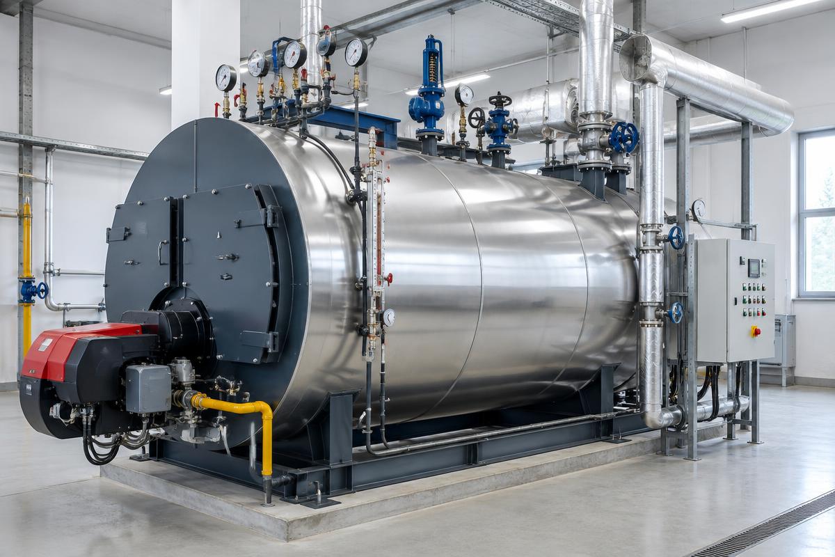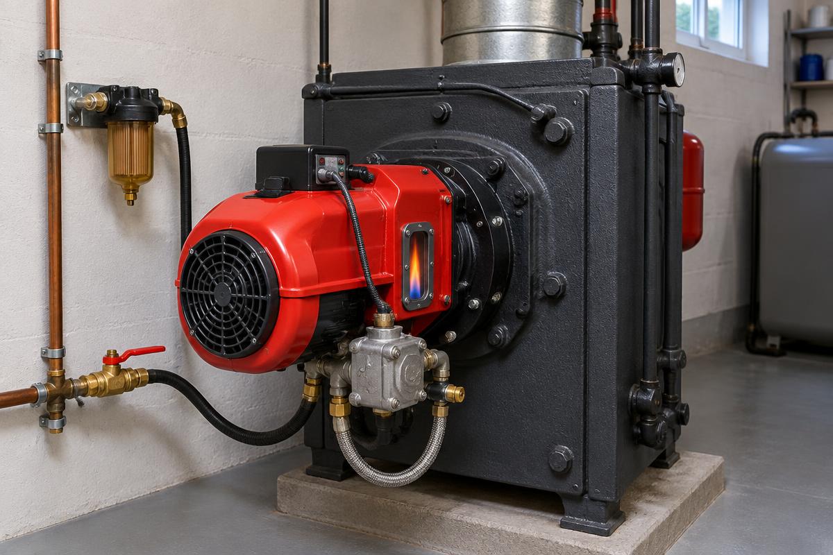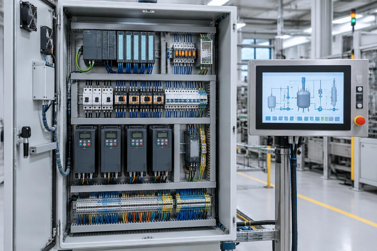
In modern industry and large heating and air conditioning facilities, the heart of the system is no longer the boiler or the chiller, but the control panel. The transition from simple relays to Programmable Logic Controllers (PLCs) has revolutionized precision and efficiency. However, the complexity of these systems requires deep knowledge from the technician, as a minor failure in a sensor can shut down an entire production line or a building.
The role of the PLC in modern automation
The PLC (Programmable Logic Controller) is essentially an industrial computer designed to withstand harsh conditions, such as dust, humidity, and electromagnetic interference. Unlike a home computer, the PLC executes a continuous scan cycle that reads inputs, executes logic, and updates outputs in milliseconds.
Digital vs. Analog Inputs
- Digital inputs (DI): Accept 0 or 1 signals (e.g., a flow pressure switch or an emergency stop button).
- Analog inputs (AI): Accept varying values, usually 4-20mA or 0-10V, from temperature, pressure, or humidity sensors.
Industrial Sensors: The eyes of the system
Without accurate data, the PLC is useless. Sensors convert physical quantities into electrical signals. In the heating and industrial sectors, the most common types are:
- Temperature Sensors: PT100 and PT1000 are the most widespread due to their accuracy and long-term stability.
- Pressure Sensors (Transmitters): Used to monitor water or steam network pressure, sending a 4-20mA signal for analog pump regulation via an Inverter.
- Inductive and Photoelectric Sensors: Used primarily in packaging lines for object position detection.
Proper sensor calibration is critical. A 2-degree Celsius error in a supply sensor can increase fuel consumption by 10% annually.
Common faults in control panels and their causes
As technicians, we are often called to deal with "blind" faults that stop the system for no apparent reason. Common causes include:
1. Loose contacts and oxidation
Due to vibrations in industrial facilities, terminal screws can loosen. This causes sparking, voltage drops, or even melting of wires. Infrared thermography is the best way to detect such problems before they cause a shutdown.
2. Electromagnetic Interference (EMI)
When low-voltage signal cables are placed in the same conduit as motor power cables, interference occurs. This leads to false readings in sensors or random PLC resets. The use of shielded cables (LiYCY) and proper grounding of the shield is mandatory.
3. Power Supply Unit (PSU) failure
24VDC power supplies are the lifeblood of the panel. Power surges from the grid or capacitor aging can lead to unstable voltage, causing erratic behavior in electronic components.
Methodology for Diagnosis and Repair
To effectively address a fault, we follow a specific sequence of actions:
- Power Supply Check: We measure the input voltage (230/400V) and the control voltage (24VDC).
- Visual Inspection: We look for burnt components, the smell of overheating, or Error LEDs on the PLC.
- Loop Check: If a sensor is providing an incorrect value, we measure the mA directly at the PLC input to see if the issue lies with the sensor, the wiring, or the input card.
- Force Outputs: Via software (if access is available), we manually activate the outputs to check if contacts and motors respond.
Preventive Maintenance: The shield of production
Maintaining an industrial panel is not just about cleaning dust. It includes:
- Tightening all electrical contacts annually.
- Checking and cleaning panel ventilation filters to prevent overheating.
- Replacing the PLC backup battery (if equipped) so that the program is not lost during a power failure.
- Checking anti-vibration mounts if the panel is mounted on machinery.
Frequently Asked Questions (FAQ)
What should I do if the PLC shows a red 'SF' (System Fault) light?
A system fault usually indicates either a hardware failure in a card or a software error (e.g., division by zero). A connection with a diagnostic PC is required to read the error buffer.
Why do analog inputs often burn out?
This is usually due to a ground potential difference between the sensor and the panel, or contact between the signal cable and a phase wire. The use of signal isolators can protect expensive PLC cards.
How often should sensors be calibrated?
In critical applications (e.g., food processing or steam boilers), annual calibration with reference instruments is recommended. For general HVAC applications, a check every two years is usually sufficient.
Conclusion
Industrial automation offers immense control possibilities, but it also requires corresponding responsibility in maintenance. Understanding the signal flow from the sensor to the PLC and paying meticulous attention to panel wiring are the keys to a reliable installation without unexpected downtime.