
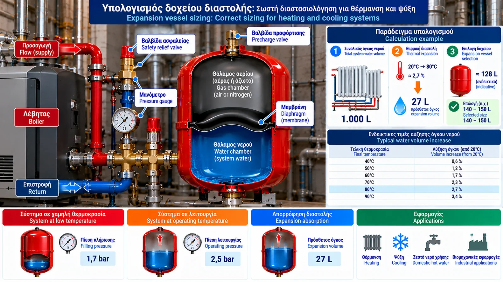
Expansion Vessel Sizing: How to Calculate Capacity for Heating and Cooling Systems
Correct expansion vessel sizing is essential for safe and reliable operation of closed hydronic heating and cooling systems.
An undersized vessel can cause excessive pressure rise, safety relief valve discharge and water loss. Incorrect precharge pressure can also reduce the effective expansion acceptance capacity, even when the nominal vessel size appears adequate.
Selection should not be based solely on boiler capacity in kW. It requires hydraulic, thermal and pressure data.
1. What Are We Calculating?
The objective is to select a vessel capable of accommodating the expected fluid volume increase without exceeding the permitted system pressure.
Required information includes:
Total system water volume.
Initial and maximum temperatures.
Fluid properties.
System static height.
Vessel precharge pressure.
System filling pressure.
Maximum design operating pressure.
Safety relief valve setting.
Any required water reserve and additional design allowances.
2. Step One: Determine Total System Water Volume
Total system volume includes all water contained within the connected closed circuit.
For example:
Component | Volume |
|---|---|
Boiler | 80 L |
Radiators | 350 L |
Pipework | 270 L |
Buffer tank | 300 L |
Total | 1,000 L |
These are hypothetical values for illustration.
Actual volume should be determined from equipment data, pipe dimensions or appropriate measurement.
3. Step Two: Calculate Thermal Expansion
Water density changes with temperature, resulting in a change in volume.
Expansion volume is:
Ve = Vs × e
Where:
Ve: Thermal expansion volume, litres.
Vs: Total system volume, litres.
e: Relative volume increase between initial and final temperatures.
The expansion coefficient can be calculated from density:
e = ρ(Tinitial) / ρ(Tfinal) − 1
This assumes constant fluid mass.
Approximate water volume increases relative to 20°C are:
Final Temperature | Approximate Volume Increase |
|---|---|
40°C | 0.6% |
50°C | 1.2% |
60°C | 1.7% |
70°C | 2.3% |
80°C | 2.7% |
90°C | 3.4% |
These rounded values are suitable for preliminary estimates. Final engineering design should use appropriate fluid property data.
4. Step Three: Calculate Static Pressure
Static height affects the minimum pressure required at the vessel connection.
For water:
pstatic ≈ H / 10
Where:
pstatic: Hydrostatic pressure, bar.
H: Elevation difference, metres.
For a 12-metre height:
pstatic ≈ 12 / 10 = 1.2 bar
This value does not automatically determine precharge pressure.
Minimum pressure requirements at the highest point, vessel location and manufacturer guidance must also be considered.
5. Step Four: Determine Precharge Pressure
Precharge is the gas pressure inside the vessel when the water side is not pressurized.
Correct precharge establishes the initial operating condition.
If precharge is too low, the vessel may already contain excessive water when the system is cold.
If precharge is too high relative to filling pressure, water may not enter the vessel sufficiently at the initial operating condition.
Precharge must be established using the system design and manufacturer instructions.
6. Step Five: Determine Filling Pressure
Filling pressure is the system pressure at the specified initial condition, usually when the water is relatively cool.
It must maintain sufficient pressure at the highest points in the circuit.
In many configurations, filling pressure is selected slightly above precharge to provide an initial water reserve in the vessel.
The appropriate difference depends on the design method and manufacturer.
7. Step Six: Establish Maximum Operating Pressure
The maximum pressure used for sizing should be below the pressure that would cause unwanted safety relief valve operation.
The valve's nominal opening pressure should not automatically be used as the maximum normal operating pressure.
An appropriate margin is required under the applicable design method.
Pressure limits of all system components must also be respected.
8. Why Absolute Pressure Matters
Gas compression relationships require absolute pressure.
For approximate calculations near normal atmospheric pressure:
pabsolute ≈ pgauge + 1 bar
Examples:
1.5 bar(g) ≈ 2.5 bar(a).
2.0 bar(g) ≈ 3.0 bar(a).
2.5 bar(g) ≈ 3.5 bar(a).
Using gauge pressure directly in gas compression equations produces incorrect results.
9. Expansion Acceptance Calculation
Under a simplified isothermal model, gas compression follows:
p × V = constant
Let:
Vn: Nominal vessel volume.
P0: Absolute precharge pressure.
P1: Absolute initial filling pressure.
P2: Absolute maximum operating pressure.
Assuming the vessel initially contains a gas volume equal to Vn, its additional water acceptance between P1 and P2 is:
Vaccept = Vn × P0 × (1/P1 − 1/P2)
This relationship applies when P1 ≥ P0 and under the stated simplified ideal-gas assumptions.
When P1 = P0:
Vaccept = Vn × (1 − P0/P2)
Actual vessel selection must be verified against manufacturer data and application requirements.
10. Complete Sizing Example
Consider a closed heating system with:
Parameter | Value |
|---|---|
Total water volume | 1,000 L |
Initial temperature | 20°C |
Maximum temperature | 80°C |
Static height | 12 m |
Precharge pressure | 1.5 bar(g) |
Filling pressure | 1.7 bar(g) |
Maximum calculation pressure | 2.5 bar(g) |
Safety relief valve setting | 3.0 bar(g) |
These pressures are illustrative assumptions, not universal recommended settings.
Step A — Thermal Expansion
For heating from 20°C to 80°C:
e = 0.027
Therefore:
Ve = 1,000 × 0.027 = 27 L
Step B — Convert to Absolute Pressures
P0 = 1.5 + 1 = 2.5 bar(a).
P1 = 1.7 + 1 = 2.7 bar(a).
P2 = 2.5 + 1 = 3.5 bar(a).
Step C — Acceptance Factor
f = P0 × (1/P1 − 1/P2)
f = 2.5 × (1/2.7 − 1/3.5)
f ≈ 0.2116
Under these assumptions, approximately 21.16% of nominal vessel volume is available for additional thermal expansion between the two pressures.
Step D — Minimum Theoretical Vessel Volume
Vn = Ve / f
Vn = 27 / 0.2116 ≈ 127.6 L
The theoretical required nominal volume is approximately 128 litres under the stated assumptions.
Step E — Select a Commercial Vessel
A nominal 140-litre or 150-litre vessel could be considered as a candidate if commercially available and suitable.
This is not automatically a final selection.
Before procurement, verify:
Any additional required water reserve.
Safety and design allowances.
Actual acceptance capacity of the selected vessel.
Permitted pressure and temperature limits.
EN 12828 requirements and manufacturer guidance.
Additional required acceptance volume may increase the final vessel size.
11. What Happens If the Vessel Is Too Small?
Consider the same system with an 80-litre vessel.
Its theoretical additional acceptance is:
Vaccept = 80 × 0.2116 ≈ 16.9 L
However, the system requires approximately 27 litres of thermal expansion capacity.
The vessel therefore cannot accommodate the expected expansion within the selected pressure range.
System pressure may exceed the intended maximum.
12. Benefits of a Larger Vessel
A larger vessel may:
Reduce pressure variation during heating.
Increase available expansion acceptance.
Provide additional design flexibility.
However, oversizing increases cost and space requirements.
The correct choice is a vessel that meets verified system requirements without unnecessary excess.
13. Expansion Vessel Sizing in Cooling Systems
The sizing method is similar for closed cooling circuits, but operating temperatures differ.
For example, a circuit may operate between 6°C and 35°C depending on operating and standby conditions.
Fluid expansion must be calculated over the actual temperature range.
Special attention is required when antifreeze mixtures are used.
14. Water–Glycol Expansion Vessels
Water–glycol mixtures have different density and thermal expansion properties from pure water.
Correct calculations require:
Glycol type.
Concentration.
Minimum temperature.
Maximum temperature.
Density data for the specific mixture.
Using pure-water expansion coefficients for a glycol system can result in incorrect vessel selection.
15. Expansion Vessels in Heat Pump Installations
Heat pump systems require assessment of total connected hydraulic volume.
This may include:
Heat pump heat exchanger.
Pipework.
Underfloor heating.
Fan coil units.
Buffer tank.
Additional hydraulic components.
An integrated expansion vessel inside a heat pump does not necessarily provide sufficient capacity for every installation.
16. Expansion Vessel and Safety Relief Valve
The safety relief valve provides overpressure protection.
The expansion vessel must accommodate normal thermal expansion without requiring regular relief valve discharge.
Maximum design pressure should include an appropriate margin below relief valve activation according to applicable requirements.
Increasing the relief valve setting merely to compensate for an undersized vessel is not acceptable.
17. Common Sizing Mistakes
Common mistakes include:
Selecting vessel size only from boiler kW.
Omitting pipework or buffer tank volume.
Using incorrect thermal expansion coefficients.
Confusing gauge and absolute pressure.
Ignoring precharge pressure.
Setting filling pressure too high.
Insufficient margin below safety valve pressure.
Omitting required reserve volume.
Failing to verify actual vessel limits.
Using water properties for glycol mixtures.
18. When Should Sizing Be Rechecked?
Reassessment is recommended when:
A buffer tank is added.
Pipework is extended.
Radiators or other loads are added.
Operating temperatures change significantly.
Filling pressure changes.
Vessel location changes.
A different heat transfer fluid is used.
Repeated pressure fluctuations or relief valve discharges occur.
19. Engineering Sizing Data Sheet
Parameter | Unit |
|---|---|
Total system volume | L |
Initial temperature | °C |
Maximum temperature | °C |
Expansion coefficient | — |
Thermal expansion volume | L |
Static height | m |
Precharge pressure | bar(g) |
Filling pressure | bar(g) |
Maximum calculation pressure | bar(g) |
Safety relief valve setting | bar(g) |
Additional required reserve | L |
Calculated nominal vessel volume | L |
Selected vessel | L |
Recording these parameters supports verification and future recalculation.
20. Standards and Technical References
Relevant references include:
EN 12828: Heating systems in buildings — Design for water-based heating systems.
EN 13831: Closed expansion vessels with built-in diaphragm for installation in water systems.
Directive 2014/68/EU (PED): Pressure equipment requirements, where applicable.
Manufacturer sizing manuals: Selection methods, acceptance data and operating limits.
Applicable editions and requirements must be confirmed for each installation.
Conclusion
Correct expansion vessel sizing depends on system water volume, thermal expansion, static pressure, precharge and the permitted pressure range.
The thermal expansion equation provides the additional fluid volume, while vessel capacity is determined by its actual acceptance capability over the operating pressure range.
Final selection should be verified using an appropriate design method, manufacturer data and applicable safety requirements.