
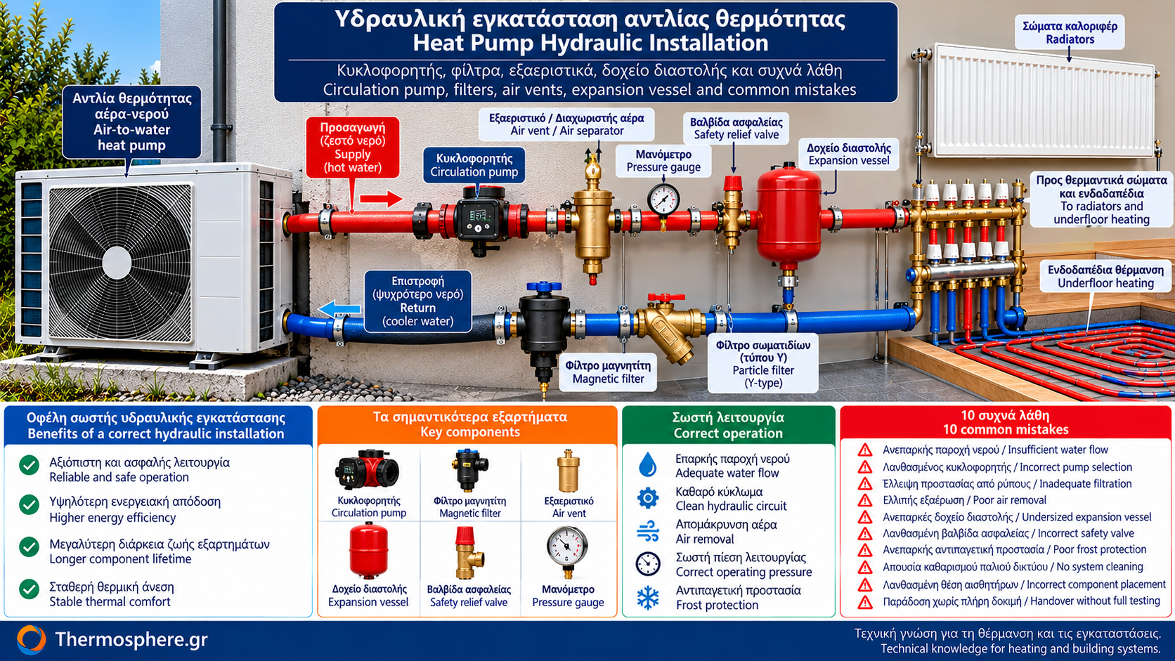
Heat Pump Hydraulic Installation: Circulation Pumps, Filters and 10 Common Mistakes
Correct hydraulic installation is essential for the reliable, safe and efficient operation of an air-to-water heat pump.
Selecting a modern heat pump with a high coefficient of performance is not enough. Actual system performance depends on proper water circulation, circuit cleanliness, air removal, pressure management and coordination between components.
An unsuitable circulation pump, blocked filter or incorrectly adjusted valve can cause operating interruptions, noise, inadequate heating and increased electricity consumption.
This guide examines the most important hydraulic components, how they operate, common problems and the checks required before handing over an installation.
1. Which Components Are Included in a Hydraulic Installation?
A typical air-to-water heat pump installation may include:
Water circulation pump.
Particle filter or magnetic dirt separator.
Air separator and automatic air vents.
Expansion vessel.
Pressure relief valve.
Pressure gauge or pressure sensor.
Isolation valves.
Filling and draining arrangements.
Suitable pipework and insulation.
Frost protection devices where required.
Some components may already be integrated into the heat pump.
Before adding external equipment, the hydraulic diagram and built-in components of the specific unit must be checked.
2. What Is the Role of the Circulation Pump?
The circulation pump moves water between the heat pump and the heating system.
It generates the differential pressure needed to overcome hydraulic resistance in the pipework and components.
Its operation affects:
Water flow rate.
Heat transfer.
Supply-to-return temperature difference.
Flow protection functions.
The circulation pump’s own electricity consumption.
Insufficient circulation may cause low-flow errors and operating interruptions.
3. How Is the Correct Circulation Pump Selected?
Selection is based on two main parameters:
Water flow rate (Q): The volume of water that must circulate per unit of time.
Pump head (H): The differential pressure required to overcome hydraulic resistance.
The pump must deliver the required flow at the actual system head.
For example, assume an installation requires:
Flow rate: 1.7 m³/h.
Pressure loss: 35 kPa.
For water, the corresponding pump head is approximately:
H = 35 / 9.81 = 3.57 mH₂O
A suitable pump must cover this operating point.
Selection is verified using the manufacturer’s performance curve.
Maximum head alone is not sufficient.
4. Integrated or External Circulation Pump?
Many modern heat pumps include an integrated circulation pump.
In these cases, the available external pump head must be checked.
Part of the pressure generated by the pump is already used to overcome resistance inside the unit.
Adding a second pump is not automatically the correct solution to low water flow.
Two pumps operating in an unsuitable arrangement may create unwanted hydraulic interaction.
The need for an additional pump must be established by the hydraulic design.
5. How Is an Electronic Circulation Pump Configured?
Modern circulators may offer control modes such as:
Constant speed.
Constant differential pressure.
Proportional differential pressure.
Control by the heat pump’s electronic controller.
The appropriate setting depends on the installation type.
For example, a variable-flow circuit may require a different strategy from a circuit that must maintain a specific minimum flow.
Factory settings should not be changed without checking manufacturer requirements.
6. What Is Magnetite?
Magnetite is an iron oxide that may form in hydraulic systems containing ferrous metal components.
It often appears as fine black sludge.
Accumulation can affect:
Circulation pumps.
Heat exchangers.
Valves.
Filters.
Sensors and hydraulic components.
A suitable magnetic filter or dirt separator can capture some of these contaminants.
Protection is particularly important when connecting a new heat pump to an older heating network.
7. Where Should a Magnetic Filter Be Installed?
In many systems, the filter is installed on the return line to the heat pump to reduce the amount of debris entering the unit’s heat exchanger.
However, its exact position depends on:
The hydraulic diagram.
Manufacturer instructions.
Filter type.
Flow direction.
Maintenance accessibility.
The arrangement should allow safe isolation and cleaning.
A magnetic dirt separator does not necessarily replace the mechanical strainer or Y-filter required by the heat pump manufacturer.
8. How Often Should the Filter Be Cleaned?
Cleaning frequency depends on network condition and manufacturer instructions.
Older installations may require more frequent checks initially.
Signs that inspection may be needed include:
Reduced water flow.
Increased pressure drop across the filter, where measurable.
Repeated flow faults.
Significant debris found during previous cleaning.
Cleaning must follow component instructions and appropriate precautions for pressure and temperature.
9. Why Does Air Accumulate in the Circuit?
Air can remain trapped after filling or enter because of leakage and operating problems.
Dissolved gases may also be released from water as temperature and pressure change.
Air in the system may cause:
Noise.
Unstable circulation.
Reduced radiator performance.
Circulation pump problems.
Difficulty maintaining normal operation.
Correct filling and venting are essential during commissioning.
10. Automatic Air Vents and Air Separators
An automatic air vent allows accumulated air to escape from suitable points in the circuit.
An air separator is designed to remove microbubbles carried by the water.
These devices do not necessarily perform the same function or offer the same effectiveness.
Their locations must follow the system design and manufacturer instructions.
Installing air vents indiscriminately at points where negative pressure may occur can create additional problems.
11. What Does an Expansion Vessel Do?
Water expands as its temperature rises.
In a closed hydraulic circuit, thermal expansion can increase pressure.
An expansion vessel accommodates part of this volume change using compressible gas, usually separated from the water by a diaphragm.
It therefore helps maintain pressure within acceptable limits.
An expansion vessel should not be confused with a buffer tank.
The expansion vessel primarily manages thermal expansion and pressure.
A buffer tank provides thermal capacity and, depending on its connection, hydraulic separation.
12. When Is an Additional Expansion Vessel Needed?
Some heat pumps include an integrated expansion vessel.
However, this does not mean that its capacity is sufficient for every installation.
Suitability depends on:
Total water volume.
Operating temperatures.
Filling pressure.
Static height.
Vessel pre-charge pressure.
System operating limits.
Larger networks may require an additional vessel.
Sizing and adjustment must be calculated rather than guessed.
13. What Does a Pressure Relief Valve Do?
A pressure relief valve protects the circuit against excessive pressure.
When pressure reaches its specified opening value, the valve can discharge water.
The valve setting must be compatible with equipment limits and system requirements.
Not every installation necessarily uses the same pressure rating.
The discharge arrangement must follow safety requirements and installation instructions.
The valve must not be isolated in a way that defeats its protective function.
14. Why Is a Pressure Gauge Important?
A pressure gauge allows monitoring of hydraulic circuit pressure.
The appropriate filling pressure depends on the installation configuration.
Pressure that is too low can cause circulation or operating problems.
Excessively high pressure may activate the safety relief valve.
If pressure changes abnormally between cold and hot conditions, the expansion vessel and other possible causes should be investigated.
15. Which Isolation Valves Are Required?
Isolation valves facilitate maintenance and component replacement.
They can allow isolation of:
Filters.
Circulation pumps.
Sections of the network.
Other serviceable components.
However, their positions require careful design.
They must not allow essential safety devices to be unintentionally isolated or minimum required circulation to be interrupted during operation.
16. What About Frost Protection?
Frost protection is especially important for monobloc heat pumps, where hydraulic circuit water may circulate through the outdoor unit.
During power outages or prolonged shutdowns, water may be at risk of freezing.
Depending on the unit and installation, protection may involve:
Approved antifreeze solution.
Dedicated antifreeze valves.
Suitable pipe insulation and protection.
Manufacturer-defined circulation and control functions.
Insulation alone cannot guarantee protection against prolonged freezing conditions.
The selected solution must comply with manufacturer instructions.
17. The 10 Most Common Installation Mistakes
Mistake 1: Insufficient Water Flow
This can cause flow errors, unstable operation and shutdowns.
Prevention: Verify required flow during commissioning.
Mistake 2: Incorrect Circulation Pump Selection
A pump may have adequate maximum head but fail to meet the actual operating point.
Prevention: Check the pump’s flow-versus-head performance curve.
Mistake 3: Inadequate Particle Protection
Dirt and magnetite can affect the heat exchanger and hydraulic components.
Prevention: Provide suitable filtration according to unit requirements.
Mistake 4: Incomplete Air Removal
Trapped air can cause noise and unstable circulation.
Prevention: Fill, vent and test the system correctly.
Mistake 5: Undersized Expansion Vessel
Pressure may rise excessively as the water heats up.
Prevention: Calculate vessel capacity and set the correct pre-charge.
Mistake 6: Incorrect Pressure Relief Valve Installation
Overpressure protection may be compromised.
Prevention: Install according to safety requirements and the approved hydraulic design.
Mistake 7: Inadequate Frost Protection
This can cause serious damage to outdoor hydraulic components.
Prevention: Select protection suitable for the unit and local climate.
Mistake 8: Failing to Clean an Existing Heating Network
Connecting a new heat pump to a contaminated system can transfer debris into the new equipment.
Prevention: Inspect, clean and treat the system water where required.
Mistake 9: Incorrect Sensor or Component Placement
This can affect control performance and measurement reliability.
Prevention: Follow the manufacturer-approved hydraulic layout.
Mistake 10: Handing Over Without Complete Functional Testing
Problems may emerge when heating demand changes or zones close.
Prevention: Test representative operating conditions and record key measurements.
18. How Does Water Quality Affect the Installation?
Water quality influences long-term system operation.
Potential problems include:
Corrosion.
Sludge formation.
Scale deposits.
Blocked filters.
Component deterioration.
Water treatment must follow manufacturer requirements and applicable technical standards.
Adding chemicals or antifreeze products without checking compatibility is not appropriate.
19. Practical Troubleshooting Table
Symptom | Possible causes |
Low-flow error | Filter, trapped air, pump, closed valve |
Pipework noise | Air, high velocity, hydraulic resistance |
Excessive pressure increase during heating | Expansion vessel, pre-charge, filling pressure |
Frequent relief valve discharge | Overpressure, expansion problem, valve issue |
Inadequate heating | Low flow, control settings, heating demand |
Repeated need to top up water | Possible leak or water loss |
Symptoms alone are insufficient for a definitive diagnosis. The installation must be inspected.
20. Commissioning Checklist
Before handing over the installation, the technician should verify:
☐ Hydraulic connections match the manufacturer-approved layout.
☐ Water cleanliness and suitability.
☐ Correct filling and air removal.
☐ Adequate water flow.
☐ Correct circulation pump operation.
☐ Proper filter placement and cleanliness.
☐ Correctly sized and adjusted expansion vessel.
☐ Functioning safety devices.
☐ Appropriate frost protection.
☐ Watertight pipes and connections.
☐ Correct thermal insulation.
☐ Functional testing under different loads.
☐ Recorded settings and operating measurements.
☐ Owner instructions for maintenance requirements.
21. Frequently Asked Questions
Does Every Heat Pump Need an External Circulation Pump?
No. Many units have an integrated pump capable of meeting system requirements.
Is a Magnetic Filter Necessary?
The required protection depends on manufacturer specifications and installation characteristics. It is particularly useful in older systems with ferrous components.
Where Should the Filter Be Installed?
Often on the return to the heat pump, but the final position must follow the approved hydraulic diagram.
Why Is There Water Noise in the Pipes?
Possible causes include trapped air or unsuitable flow velocity.
Is a Second Expansion Vessel Needed?
Only if calculations show that the existing vessel is insufficient.
Why Does Pressure Rise During Heating?
Some pressure change due to thermal expansion is expected. Excessive increases require investigation.
Can I Clean the Filter Myself?
The procedure depends on the filter type. Since the circuit may be pressurized and hot, the manufacturer’s instructions and appropriate technical precautions must be followed.
What Is the Most Important Installation Requirement?
Overall compatibility between the hydraulic system and the heat pump’s operating requirements.
Conclusion
Correct hydraulic installation depends on more than a single component.
The circulation pump must deliver the required flow, filters must protect the system, air vents must remove trapped air, and the expansion vessel must help manage pressure.
Safety devices, water quality and frost protection are also integral parts of the design.
An efficient installation is not the one with the most components, but the one in which every component has been correctly selected, positioned and configured.
This article provides technical information and does not replace installation design, manufacturer instructions or work by qualified professionals.
Thermosphere.gr — Technical knowledge for heating and building systems.