
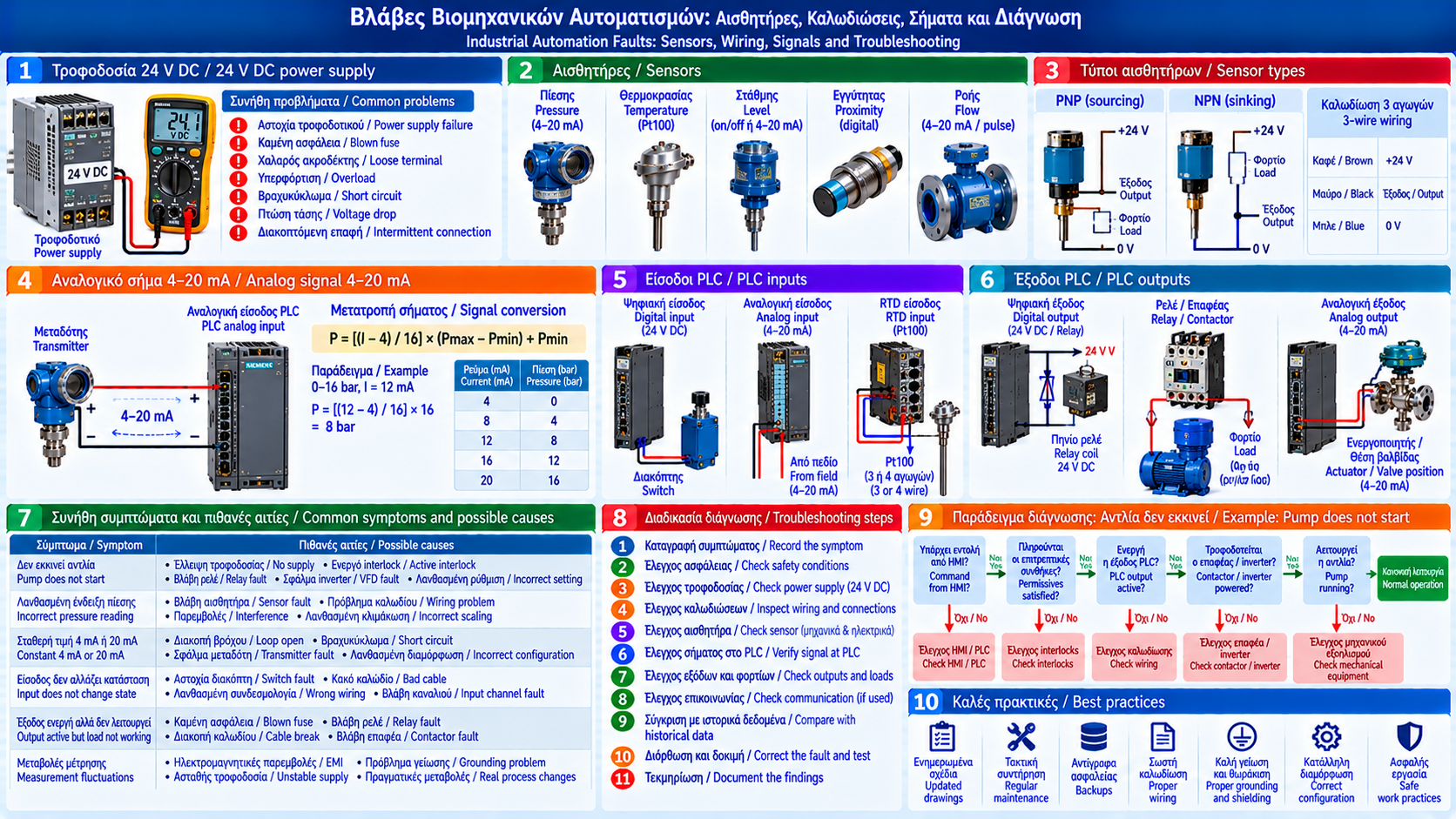
# Industrial Automation Faults: Sensors, Wiring, Signals and Troubleshooting
## Introduction
Industrial automation faults can interrupt production, generate incorrect measurements and cause unwanted equipment starts, stops or malfunctions.
When a pump fails to start, a valve does not open or a pressure indication becomes unstable, the PLC is not necessarily responsible.
The cause may be a sensor, wiring, power supply, input/output module, actuator or an actual process condition.
Effective troubleshooting requires systematic investigation, accurate documentation and safe electrical practices.
## 1. Main Categories of Automation Faults
Automation faults can be grouped into:
- Power supply problems.
- Sensor failures.
- Wiring and connection faults.
- Digital input problems.
- Analog signal problems.
- PLC module faults.
- Relay and contactor failures.
- Actuator problems.
- Communication faults.
- Incorrect settings or control logic.
An HMI alarm is a symptom that must be evaluated against actual operating data.
## 2. Why Should the PLC Not Be Blamed Immediately?
A PLC may operate correctly while receiving incorrect field information.
Example:
A tank has sufficient liquid level, but the low-level switch remains active.
The PLC prevents pump startup according to its programmed protection logic.
In this case, the PLC may be functioning correctly. The actual problem could be a defective sensor, damaged wire or incorrect connection.
Inputs, outputs and permissives should be checked before replacing any controller module.
## 3. First Step: Record the Symptoms
Troubleshooting begins with specific questions:
- Which machine is affected?
- When did the problem appear?
- Is it continuous or intermittent?
- Is an alarm active?
- When did the machine last operate correctly?
- Was maintenance or configuration work performed recently?
- Are other devices affected?
- What measurements are displayed on the HMI?
Recording timestamps and related alarms helps correlate events with historical data.
## 4. Checking the 24 V DC Power Supply
Many industrial sensors, I/O modules and control circuits use 24 V DC power.
Possible problems include:
- Power supply failure.
- Blown fuse.
- Loose terminal.
- Overloading.
- Short circuit.
- Cable voltage drop.
- Intermittent connection.
A nominal 24 V DC rating does not mean every device has exactly the same allowable voltage range.
Measurements must be compared with the relevant device specifications.
Testing under load may reveal problems not visible during no-load measurements.
## 5. PLC Digital Inputs
Digital inputs represent ON/OFF conditions.
Examples include:
- Limit switches.
- Pressure switch contacts.
- Contactor auxiliary contacts.
- Level switches.
- VFD fault indications.
- Valve position signals.
If an input does not change state, possible causes include:
- Defective switch.
- Disconnected wire.
- Missing supply voltage.
- Incorrect polarity or wiring.
- Common-reference problems.
- Faulty input channel.
Input LEDs are useful diagnostic indicators but do not replace verification of the actual condition.
## 6. PNP and NPN Sensors
PNP and NPN sensors differ in how their outputs switch.
In a typical three-wire DC arrangement:
- A PNP sensor supplies positive voltage to the load when activated.
- An NPN sensor switches its output toward the negative supply potential when activated.
The PLC input module must be compatible with the sensor wiring.
Replacing a sensor with a different output type may cause malfunction even when both use the same nominal voltage.
Always verify the datasheet and electrical drawing.
## 7. Analog 4–20 mA Signals
The 4–20 mA standard is widely used to transmit process measurements.
For a linearly configured transmitter:
- 4 mA represents the lower range limit.
- 20 mA represents the upper range limit.
- Intermediate currents represent proportional process values.
Example:
A pressure transmitter has a range of 0–16 bar.
At 12 mA:
P = [(12 − 4) / 16] × 16 = 8 bar.
This scaling applies when the transmitter output is linear and configured for the stated range.
## 8. What Do 0 mA, 3.6 mA and 21 mA Mean?
Out-of-range current values may have different interpretations.
A reading near 0 mA may be associated with an open loop, missing supply or another electrical condition.
Devices configured according to NAMUR NE 43 may use low or high currents to indicate faults.
However, exact thresholds and behavior depend on the manufacturer and configuration.
A current of 3.6 mA or 21 mA must not automatically be assigned one universal meaning.
Consult the transmitter documentation and settings.
## 9. Two-Wire and Four-Wire Transmitters
Transmitters use different power and signal arrangements.
### Two-Wire Transmitters
Often receive power through the same 4–20 mA loop.
### Four-Wire Transmitters
Use separate power supply and output connections.
Correct wiring depends on output type, isolation and input module architecture.
Incorrect connections may cause signal loss or equipment damage.
## 10. Pressure Sensor Faults
Common symptoms include:
- Zero indication despite actual pressure.
- Constant reading during process changes.
- Irregular fluctuations.
- Out-of-range values.
- Slow response.
Potential causes include:
- Sensor failure.
- Blocked process connection.
- Incorrect calibration.
- Power supply problems.
- Poor electrical connection.
- Actual pressure instability.
Diagnosis may require comparison with an appropriate independent measurement where safe and permitted.
## 11. Temperature Sensor Faults
Temperature sensors include RTDs and thermocouples.
Possible problems include:
- Broken conductors.
- Short circuits.
- Incorrect sensor type configuration.
- Poor thermal contact.
- Faulty transmitters.
- Electromagnetic interference.
For RTDs such as Pt100, resistance changes with temperature.
Correct interpretation requires suitable instrumentation, knowledge of two-, three- or four-wire connections, and the relevant sensor specifications.
Do not apply arbitrary voltage to RTD or thermocouple inputs.
## 12. Level Sensor Faults
Level measurement technologies include:
- Float switches.
- Hydrostatic pressure.
- Ultrasonic sensors.
- Radar.
- Capacitive sensing.
- Other measurement methods.
Potential problems include:
- Deposits.
- Foam.
- Moisture in electrical connections.
- Improper installation.
- Incorrect configuration.
- Mechanical float obstruction.
Assessment must consider the measurement technology and liquid properties.
## 13. Wiring Problems
Wiring is a common source of intermittent faults.
Potential issues include:
- Loose terminals.
- Oxidation.
- Damaged insulation.
- Moisture.
- Mechanical stress.
- Improper shielding.
- Incorrect cable routing.
- Poor grounding or bonding.
Inspection should follow electrical drawings and approved isolation procedures.
High-voltage insulation testing must not be performed on connected electronics without appropriate disconnection instructions.
## 14. Electromagnetic Interference
Electromagnetic interference can affect automation signals.
Potential sources include:
- Variable-frequency drives.
- Contactor switching.
- Power cables.
- Improper grounding.
- Inadequate shielding.
- High transient currents.
Symptoms may include momentary measurement fluctuations or communication interruptions.
Corrective measures must follow equipment installation and electromagnetic compatibility guidance.
## 15. PLC Digital Output Faults
A digital output may appear active in the program while the connected load remains inactive.
Possible causes include:
- Blown output fuse.
- Missing external supply.
- Faulty intermediate relay.
- Broken wire.
- Failed coil.
- Active local protection.
- Defective output channel.
Troubleshooting must distinguish the logical command state from the actual electrical condition of the circuit.
## 16. Relay and Contactor Faults
Possible symptoms include:
- Coil does not energize.
- Contactor energizes but the load does not operate.
- Unusual noise.
- Overheating.
- Worn contacts.
- Intermittent operation.
Causes may include incorrect coil voltage, mechanical wear, contact problems or poor connections.
Inspection and replacement must follow equipment specifications and electrical safety procedures.
## 17. Actuator and Valve Faults
A valve may receive an open command but fail to move.
Possible causes include:
- Missing power supply.
- Insufficient instrument air pressure.
- Faulty solenoid valve.
- Mechanical obstruction.
- Limit switch problems.
- Electric actuator failure.
- Incorrect configuration.
Diagnosis should verify both the command and the actual position or operation.
## 18. Example: Pump Fails to Start
An operator presses START on the HMI, but the pump remains stopped.
A structured investigation checks:
1. Whether the command reaches the PLC.
2. Whether the correct Auto/Manual mode is selected.
3. Whether permissives are satisfied.
4. Whether an interlock or protection is active.
5. Whether the startup circuit receives a command.
6. Whether the contactor or VFD is available.
7. Whether appropriate running feedback is present.
8. Whether the pump delivers the required hydraulic performance.
The sequence must be adapted to the specific architecture and performed safely.
## 19. Example: Pressure Reading Changes Suddenly
A pressure transmitter shows sudden fluctuations on the HMI.
Possible explanations include:
- Actual process fluctuations.
- Power supply problems.
- Poor electrical connections.
- Electromagnetic interference.
- Faulty transmitter.
- Analog input problems.
- Incorrect scaling or data processing.
Diagnosis compares actual process conditions, field signal, PLC value and HMI display.
Replacing the transmitter without confirmation may not solve the problem.
## 20. Using Historical Data for Troubleshooting
SCADA data can help identify relationships between events.
Example:
Whenever a large motor starts, an analog measurement fluctuates briefly.
This correlation may justify investigating power quality, electromagnetic interference or actual process disturbances.
Correlation alone does not establish causation.
Appropriate tests are required to confirm the cause.
## 21. Preventing Recurring Automation Faults
Preventive maintenance may include:
- Electrical cabinet inspections.
- Power supply checks.
- Connection inspections according to manufacturer guidance.
- Cable and seal inspections.
- Sensor condition checks.
- Periodic instrument verification or calibration.
- PLC program backup verification.
- Recurring alarm analysis.
- Electrical drawing updates.
- Change management.
Maintenance intervals should reflect equipment criticality and requirements.
## 22. Safety During Troubleshooting
Automation troubleshooting may involve hazardous electrical or mechanical conditions.
Key principles include:
- Work by suitably trained and authorized personnel.
- Hazardous energy isolation where required.
- Verification of absence of voltage before intervention using an approved procedure.
- Suitable test instruments.
- No unauthorized bypassing of protections.
- No unauthorized forcing of PLC outputs.
- Protection against unexpected startup.
- Documentation and approval of changes.
Live-circuit testing should only be performed when necessary and permitted by an approved safe-work procedure.
## Conclusion
Effective industrial automation troubleshooting requires understanding the entire control chain, from sensors and wiring to PLCs, actuators and the physical process.
24 V DC supplies, 4–20 mA loops, digital I/O and HMI indications must be evaluated as parts of one system.
Systematic investigation, safe working practices and accurate documentation reduce unnecessary component replacements and improve plant reliability.
Thermosphere.gr – Technical Knowledge for Professionals.