
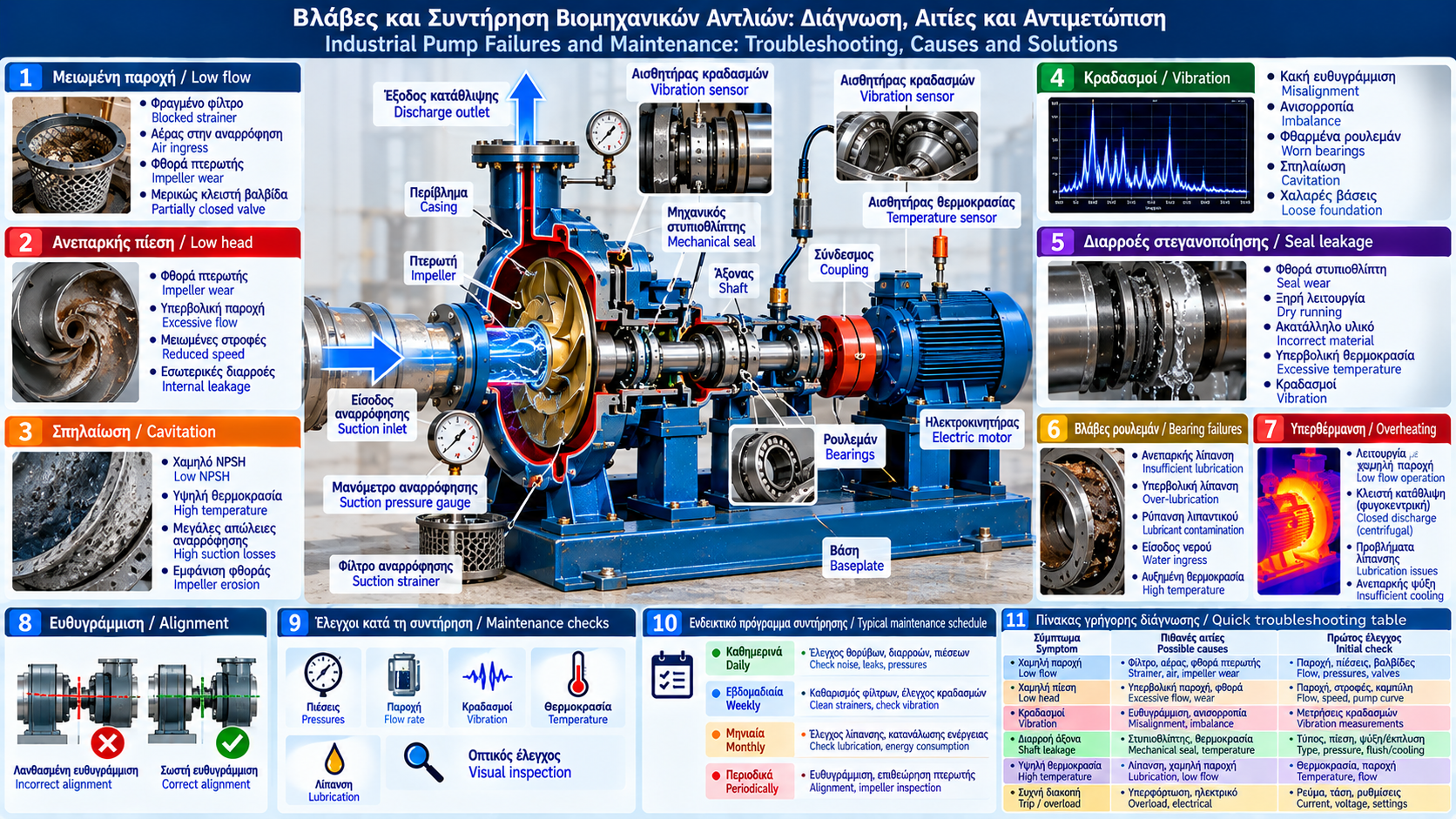
# Industrial Pump Failures and Maintenance: Troubleshooting, Causes and Solutions
## Introduction
Industrial pumps often operate for many hours every day, transferring water, hot liquids, chemical solutions and other fluids used in production processes.
Their reliability depends on correct selection, installation, hydraulic conditions and maintenance.
A failure may interrupt production, cause loss of water or product, increase energy consumption and damage connected equipment.
Effective maintenance goes beyond replacing worn components. It requires identifying the root cause of failure and verifying operating conditions.
## 1. Common Industrial Pump Failures
Typical problems include:
- Reduced or zero flow.
- Insufficient discharge pressure.
- Loss of prime or air ingress.
- Cavitation.
- Excessive vibration.
- Mechanical seal leakage.
- Bearing overheating or failure.
- Impeller wear.
- Electric motor overload.
- Repeated protective trips.
Symptoms alone do not prove a specific cause. Diagnosis requires measurements and inspection.
## 2. Reduced or Zero Flow
Possible causes of low pump flow include:
- Blocked suction strainer.
- Partially closed valve.
- Air ingress.
- Inadequate priming.
- Reverse rotation.
- Worn or obstructed impeller.
- Changes in system resistance.
- Incorrect rotational speed.
Troubleshooting begins by verifying actual flow, suction and discharge pressures and valve positions.
For centrifugal pumps, confirm that the operating point lies within the permitted range of the Q-H curve.
## 3. Insufficient Discharge Pressure
Low discharge pressure does not necessarily indicate pump damage.
Possible causes include:
- Excessive flow relative to the pump curve.
- Reduced rotational speed.
- Impeller wear.
- Internal leakage.
- Air or gas in the liquid.
- Incorrect pressure measurement.
- Changes in suction pressure.
Discharge pressure must be assessed together with suction pressure and flow.
Pressure difference alone is not a complete pump head calculation when elevation or velocity differences between measurement points are significant.
## 4. Loss of Prime and Air Ingress
Many centrifugal pumps require proper priming before startup.
Air trapped in the casing or suction line can prevent the pump from developing the required flow.
Possible causes include:
- Suction line leaks.
- Insufficient tank level.
- Inlet vortex formation.
- Poor piping geometry.
- Faulty foot valve, where installed.
Corrective action includes leak inspection, proper venting and verification of the manufacturer's priming requirements.
Not all pumps are self-priming.
## 5. Cavitation: Symptoms and Causes
Cavitation occurs when local pressure falls sufficiently for vapor bubbles to form.
Bubble collapse can erode impeller surfaces and produce mechanical loading.
Common symptoms:
- Gravel-like noise.
- Increased vibration.
- Unstable flow.
- Reduced head.
- Impeller damage.
Causes include:
- Low available NPSH.
- High liquid temperature.
- Low suction tank level.
- Excessive suction losses.
- Blocked strainer.
- Operation outside the suitable flow range.
Available NPSH must be evaluated against the manufacturer's NPSH3 and the required margin.
Noise alone does not confirm cavitation.
## 6. Excessive Pump Vibration
Vibration is an important indicator of mechanical and hydraulic condition.
Possible causes include:
- Motor-to-pump misalignment.
- Impeller imbalance.
- Worn bearings.
- Loose foundations.
- Pipe strain.
- Cavitation.
- Hydraulic recirculation.
- Structural resonance.
Diagnosis may include overall vibration velocity measurement, frequency spectrum analysis and trend monitoring.
Acceptable vibration limits depend on machine type, power, mounting and applicable specifications. No single universal limit applies to every pump.
## 7. Pump and Motor Alignment
Misalignment may cause:
- Premature bearing wear.
- Coupling stress.
- Increased vibration.
- Seal leakage.
- Higher operating temperatures.
Alignment should be performed using suitable instruments and manufacturer tolerances.
Laser alignment systems are commonly used in critical installations.
Soft foot, foundation condition, pipe strain and thermal growth should also be evaluated where relevant.
Alignment alone does not correct foundation or piping problems.
## 8. Mechanical Seals: Operation and Failures
A mechanical seal limits leakage along the rotating pump shaft.
It generally consists of:
- Rotating seal face.
- Stationary seal face.
- Secondary sealing elements.
- Springs or another loading mechanism.
- Retaining components.
Potential causes of failure include:
- Dry running.
- Inadequate face lubrication or cooling.
- Incompatible materials.
- Excessive temperature.
- Vibration.
- Incorrect installation.
- Solid particles.
- Sudden pressure changes.
Some sealing arrangements allow controlled minor leakage or require a defined auxiliary fluid flow. Acceptable conditions depend on seal design and manufacturer specifications.
## 9. What to Check When a Seal Leaks
Before intervention, safely isolate the equipment.
Then check:
1. Exact leakage location.
2. Operating pressure.
3. Liquid temperature.
4. Shaft condition.
5. Vibration.
6. Alignment.
7. Liquid cleanliness and quality.
8. Seal flushing or cooling system, where installed.
Replacing a mechanical seal without correcting the original cause may lead to repeated failure.
## 10. Pump Bearings
Bearings support the rotating shaft and carry the intended loads.
Common failure causes include:
- Insufficient lubrication.
- Excessive lubrication.
- Lubricant contamination.
- Water ingress.
- Misalignment.
- Excessive loading.
- Incorrect installation.
- Electrical bearing currents where applicable.
Symptoms include:
- Increased temperature.
- Noise.
- Changes in vibration.
- Lubricant deterioration.
- Increased power consumption in some cases.
Lubrication type, quantity and intervals must follow manufacturer recommendations.
## 11. Pump Overheating
Overheating may result from:
- Operation at insufficient flow.
- Extended closed-discharge operation in a centrifugal pump.
- Lubrication problems.
- Excessive friction.
- Inadequate cooling.
- High process temperature.
- Mechanical seizure.
For centrifugal pumps, operation near zero flow can cause the trapped liquid to heat up.
For positive displacement pumps, a closed discharge can create dangerous overpressure if suitable protection is absent.
These two conditions must not be treated as equivalent.
## 12. Electric Motor Overload
Motor overload may be caused by:
- Operation at a flow requiring high shaft power.
- Increased liquid density or viscosity.
- Mechanical friction.
- Impeller obstruction.
- Unsuitable electrical supply.
- Incorrect protection settings.
- Motor defects.
Diagnosis includes current, voltage and power measurements and review of the pump power curve.
Reducing flow does not necessarily reduce power for every pump type.
## 13. Impeller and Casing Wear
Impellers and casings may experience:
- Chemical corrosion.
- Particle erosion.
- Cavitation damage.
- Mechanical contact.
- Deposits.
- Flow passage blockage.
Wear can alter the pump performance curve and reduce efficiency.
Inspection should cover the impeller, internal clearances, wear rings where fitted and casing surfaces.
## 14. Preventive and Predictive Maintenance
Preventive maintenance is based on scheduled inspections.
Predictive maintenance relies on monitoring actual equipment condition.
Common techniques include:
- Vibration analysis.
- Thermography.
- Bearing temperature monitoring.
- Lubricant analysis.
- Flow and pressure measurement.
- Electrical power monitoring.
- Ultrasonic inspection where appropriate.
These methods help identify deterioration before complete failure.
## 15. Illustrative Inspection Schedule
### Daily or Each Shift
- Check for abnormal noise.
- Visually inspect for leakage.
- Record flow and pressures.
- Check bearing temperatures where monitored.
- Confirm normal operation of protective systems.
### Weekly
- Inspect strainers and pressure differentials.
- Compare vibration with normal baseline values.
- Inspect foundations and connections.
- Check auxiliary seal systems.
### Monthly or According to the Maintenance Plan
- Analyze operating trends.
- Review energy consumption.
- Check lubrication condition.
- Compare performance against the reference pump curve.
### Periodically
- Check alignment where required.
- Inspect impeller and internal clearances.
- Inspect coupling and seals.
- Replace components based on condition or manufacturer guidance.
These intervals are illustrative. Actual frequency depends on equipment criticality, liquid properties, operating hours and manufacturer instructions.
## 16. Quick Troubleshooting Reference
Symptom: Low flow.
Possible causes: Blocked suction, air ingress, worn impeller, incorrect speed.
Initial checks: Flow, pressures, strainer and rotation direction.
Symptom: Excessive vibration.
Possible causes: Misalignment, imbalance, bearings, cavitation.
Initial checks: Vibration measurements, operating point and foundation.
Symptom: Shaft leakage.
Possible causes: Seal failure, dry running, vibration.
Initial checks: Seal type, temperature, pressure and flushing system.
Symptom: High bearing temperature.
Possible causes: Lubrication, overloading, misalignment.
Initial checks: Temperature, lubricant and vibration.
Symptom: Repeated motor protection trips.
Possible causes: Overload, electrical faults, mechanical seizure.
Initial checks: Current, voltage, power and protection settings.
## 17. Operating Records and Failure History
An effective maintenance program requires organized equipment history.
Useful records for each pump include:
- Equipment identification.
- Manufacturer and model.
- Normal operating point.
- Flow and pressures.
- Temperature.
- Current or electrical power.
- Vibration.
- Maintenance activities.
- Replaced spare parts.
- Failure causes and corrective actions.
Comparing new measurements with historical data helps identify gradual deterioration.
## 18. Maintenance Safety
Before any work on an industrial pump:
1. Stop the equipment safely.
2. Isolate electrical and other hazardous energy.
3. Apply lockout/tagout procedures where required.
4. Isolate the pump from the process.
5. Depressurize and drain safely.
6. Check temperature.
7. Assess chemical and other hazards.
8. Verify a safe condition before dismantling.
Hot water, chemicals and hazardous liquids require additional plant-specific precautions.
## 19. Repair or Replace?
The decision should consider technical and economic factors.
Evaluate:
- Extent of damage.
- Repair feasibility.
- Spare parts availability.
- Production downtime cost.
- Energy efficiency.
- Equipment age and condition.
- Frequency of recurring failures.
- Suitability for current operating requirements.
Repeated repairs of an incorrectly selected pump may be less economical than replacement with a suitable model.
## Conclusion
Most industrial pump failures cannot be effectively addressed by replacing worn components alone.
Diagnosis should combine hydraulic measurements, vibration assessment, seal condition, lubrication, alignment and actual operating conditions.
Systematic preventive and predictive maintenance reduces unplanned downtime, improves reliability and helps preserve energy efficiency.
Thermosphere.gr – Technical Knowledge for Professionals.