
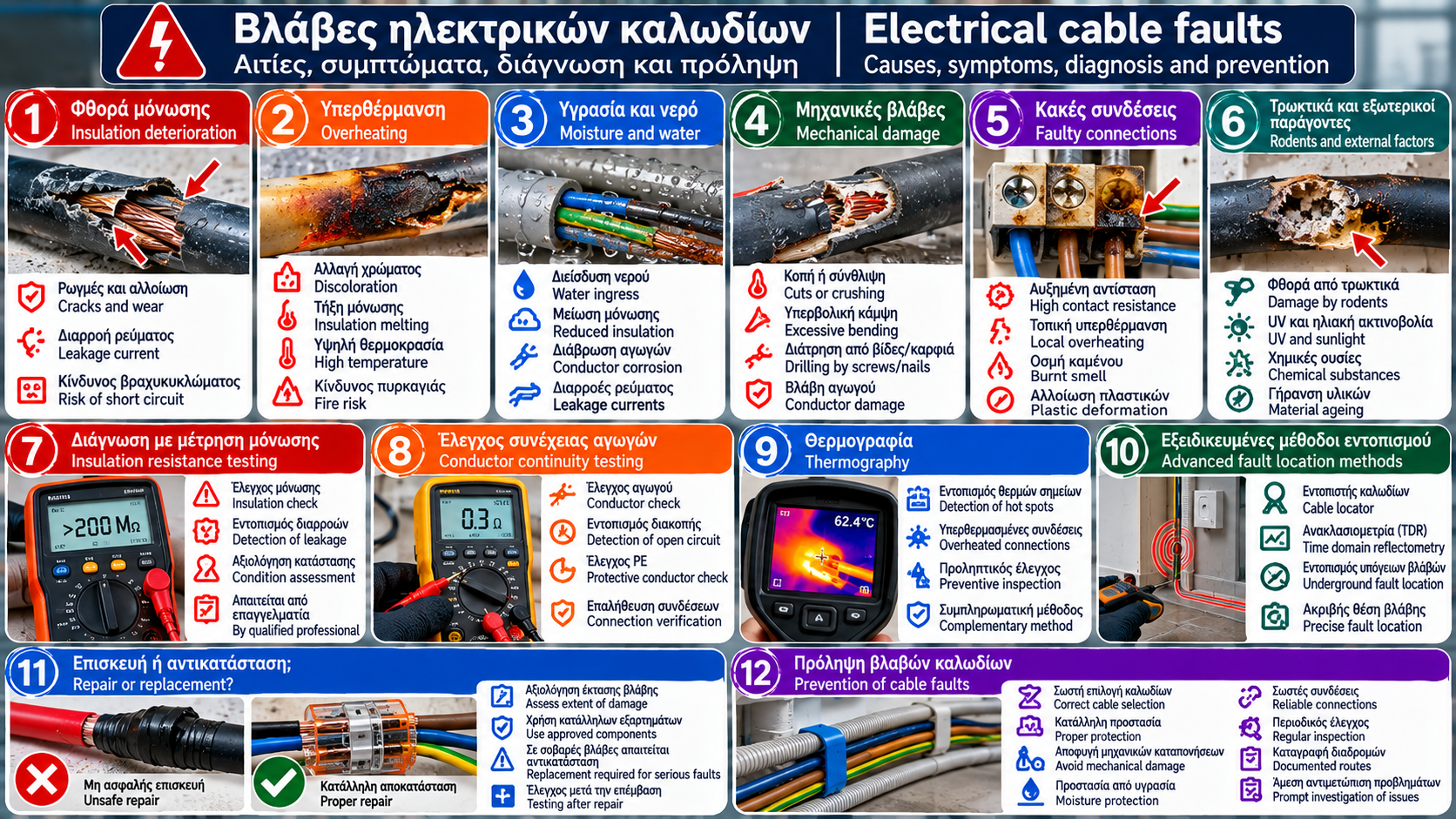
Electrical Cable Faults: Complete Guide to Insulation Damage, Overheating, Moisture and Diagnosis
Electrical cables are among the most important components of any electrical installation. They carry electrical energy from distribution boards to socket outlets, lighting fixtures, electrical appliances and permanently installed electromechanical equipment.
Although most cables are installed with the expectation that they will operate reliably for many years, they are not indestructible.
Continuous thermal stress, mechanical pressure, moisture, insulation aging and unsuitable connections can affect their electrical and mechanical integrity.
Some faults become immediately apparent, for example when a circuit stops operating. Others develop gradually and may remain hidden inside walls, conduits or junction boxes.
This guide examines the most important causes of electrical cable failure, typical symptoms, professional diagnostic methods, criteria for repair or replacement and essential preventive measures.
1. What Is an Electrical Cable Fault?
An electrical cable fault is any condition that affects a cable’s ability to carry electrical energy safely and within its intended operating conditions.
A fault may involve:
The metallic conductor.
Electrical insulation.
The outer sheath.
Connections and terminations.
Mechanical support.
Protection against environmental influences.
A cable fault does not necessarily mean that the cable has been completely severed.
A cable may continue operating while its insulation has undergone significant deterioration.
This makes periodic inspections and appropriate electrical testing particularly important.
2. Main Categories of Cable Faults
Cable faults can be classified according to the mechanisms that cause them.
Category | Typical Problem | Possible Consequence |
Insulation deterioration | Cracking, punctures, material degradation | Leakage current or short circuit |
Thermal stress | Excessive temperature | Accelerated aging |
Mechanical damage | Cutting, crushing, excessive bending | Conductor or insulation damage |
Moisture | Water ingress | Reduced insulation performance |
Corrosion | Deterioration of metallic components | Increased resistance or failure |
Poor connection | Increased contact resistance | Localized overheating |
Aging | Long-term material degradation | Reduced reliability |
External influences | UV radiation, chemicals, rodents | Sheath and insulation damage |
In practice, several causes may occur simultaneously.
3. Electrical Insulation Deterioration
Insulation electrically separates conductors from one another and from other conductive parts.
When insulation deteriorates, the risk of unintended current flow increases.
Common Causes
Excessive temperature.
Mechanical abrasion.
Moisture.
Chemical exposure.
Material aging.
Improper installation.
Manufacturing defects.
Possible Warning Signs
Cracks.
Hardening or brittleness.
Discoloration.
Deformation.
Localized melting.
Exposed conductors.
Visual appearance can provide useful indications, but it is not sufficient for a complete assessment of insulation condition.
4. Electrical Cable Overheating
Every electrical conductor has electrical resistance.
When current flows through it, some electrical energy is converted into heat.
For an ohmic conductor:
P = I² × R
Where:
P = power converted into heat, in watts (W).
I = electrical current, in amperes (A).
R = electrical resistance, in ohms (Ω).
Calculation Example
Consider a section of conductor with a resistance of 0.15 Ω.
At a current of 10 A:
P = 10² × 0.15 = 15 W
If the current increases to 15 A:
P = 15² × 0.15 = 33.75 W
Assuming constant resistance, a 50% increase in current results in a 125% increase in heat generation.
In practice, the resistance of a metallic conductor also changes with temperature.
Why Does This Matter?
Repeated operation at elevated temperatures can accelerate insulation aging.
Operating temperature must remain within the limits specified for the particular cable and its installation method.
5. Overloading and Incorrect Cable Protection
Overloading can cause excessive thermal stress.
The problem does not depend solely on conductor cross-sectional area.
It is also affected by:
Installation method.
Ambient temperature.
Cable grouping.
Insulation type.
Operating duration.
Protective device characteristics.
Example
A cable installed within thermal insulation may dissipate heat less effectively than an equivalent cable installed under more favorable cooling conditions.
Therefore, two cables with the same cross-sectional area do not necessarily have the same permissible current-carrying capacity.
Overload protection must be coordinated with the actual current-carrying capacity of the circuit.
6. Mechanical Damage to Electrical Cables
Electrical cables can experience mechanical stress during installation or throughout their service life.
Common Causes
Drilling into walls.
Screws or nails.
Crushing.
Excessive bending.
Excessive pulling force.
Abrasion against sharp edges.
Machinery movement.
Inadequate support.
What Can Happen?
Mechanical damage may cause:
Localized insulation deterioration.
Partial or complete conductor interruption.
Contact between conductors.
Contact with conductive metal parts.
Future failure caused by continued stress.
Particularly dangerous faults are those that remain concealed and do not cause an immediate interruption of operation.
7. Cable Damage Caused by Moisture and Water
Water can enter cables, connections, junction boxes and electrical equipment.
Its effects depend on cable construction, materials, environmental conditions and exposure duration.
Where Does It Commonly Occur?
Basements.
Bathrooms.
Outdoor installations.
Inspection chambers.
Pump rooms.
Underground cable routes.
Wall penetrations.
Enclosures with inadequate sealing.
Possible Consequences
Reduced insulation resistance.
Leakage currents.
Corrosion.
Connection failures.
Operation of protective devices.
A cable exposed to water must not automatically be considered safe simply because its exterior has dried.
Returning it to service requires a technical assessment.
8. Cable Aging and Service Life
The service life of an electrical cable is not determined exclusively by its installation date.
It is influenced by:
Insulation material.
Operating temperature.
Electrical stress.
Environmental conditions.
Mechanical protection.
Installation quality.
Frequency of thermal cycling.
What Happens During Aging?
Certain insulating materials may gradually lose some of their flexibility and mechanical strength.
In other cases, surface deterioration or changes in electrical properties may occur.
There is no universal replacement age applicable to every cable.
Replacement decisions should be based on actual condition and inspection results.
9. Cable Damage Caused by UV Radiation and Chemicals
Some cables are designed for outdoor exposure, while others are not.
Ultraviolet Radiation
Prolonged exposure to sunlight can degrade materials that have not been designed for such conditions.
Chemical Exposure
Oils, solvents and other chemicals may affect certain insulation or sheath materials.
Technical Approach
Cable selection must be based on the manufacturer’s declared properties and the actual exposure conditions.
A cable suitable for indoor installation is not necessarily suitable for direct sunlight or chemical exposure.
10. Cable Damage Caused by Rodents and External Factors
In storage areas, basements, suspended ceilings and other spaces, cables may be damaged by animals or external interference.
Possible Problems
Stripped insulation.
Exposed metallic conductors.
Mechanical failure.
Short circuits.
Leakage currents.
Prevention
Depending on the application, suitable measures may include:
Appropriate conduits.
Protective trunking.
Mechanically resistant cables.
Secure fixing.
Periodic inspections.
Protection must be selected according to the actual risk.
11. Poor Connections and Termination Problems
Many faults initially attributed to cables are eventually traced to their connection points.
Possible Causes
Insufficient tightening.
Unsuitable terminals.
Incompatible materials.
Improper conductor preparation.
Mechanical stress.
Corrosion.
Incorrect connector selection.
Why Does a Connection Overheat?
A defective contact may have increased electrical resistance.
Localized heat generation can damage insulation near the termination.
Warning Signs
Discoloration.
Plastic deformation.
Burning smell.
Intermittent operation.
Signs of thermal damage.
Corrective action requires investigating the underlying cause rather than simply replacing the visibly damaged component.
12. Open Conductors and Continuity Problems
An electrical conductor may become completely or partially interrupted.
Complete Interruption
This may cause immediate loss of circuit operation.
Partial Damage
This may cause:
Intermittent operation.
Increased resistance.
Localized overheating.
Voltage instability under load.
Particular Importance of the Protective Conductor
An interrupted protective conductor (PE) may not affect the normal operation of an appliance.
However, it can seriously compromise protection against electric shock.
For this reason, protective conductor continuity must be verified through appropriate testing.
13. Short Circuits Within Electrical Cables
A short circuit may occur when insulation is damaged and an unintended electrical connection develops between conductors at different electrical potentials.
Possible Causes
Mechanical penetration.
Thermal damage.
Severe insulation deterioration.
Improper connections.
Moisture ingress at vulnerable locations.
Possible Symptoms
Immediate operation of a protective device.
Loss of electrical supply.
Sparking.
Thermal damage.
The exact behavior depends on fault impedance and the characteristics of the electrical installation.
Protective devices should not be repeatedly reset without investigating the fault.
14. Leakage Current Caused by Insulation Problems
When cable insulation deteriorates, unintended current paths may develop.
Possible Indications
RCD operation.
Unstable circuit behavior.
Deterioration under humid conditions.
Unacceptable insulation resistance test results.
RCD operation alone does not prove that the cable is defective.
The cause may be an appliance, a connection or another part of the circuit.
Diagnosis requires systematic evaluation.
15. How Are Hidden Cable Faults Located?
Faults inside walls, conduits or other enclosed routes are not always visible.
Professional fault location relies on a combination of information and testing.
Stage 1: Recording Symptoms
The electrician investigates:
When the problem occurs.
Which circuits are affected.
Whether it is associated with a particular load.
Whether construction work has recently taken place.
Whether there is a history of moisture.
Stage 2: Reviewing the Installation
Available electrical drawings, cable routes and technical documentation are examined.
Stage 3: Safe Isolation
Before suitable tests are performed, the required safe isolation procedures and verification of absence of voltage are applied.
Stage 4: Targeted Measurements
Appropriate testing methods are selected according to the suspected problem.
Stage 5: Confirming the Location and Cause
The findings are evaluated before any corrective intervention is decided.
16. Cable Insulation Resistance Testing
Insulation resistance testing is used to assess the electrical insulation of an installation or circuit.
It is performed using a suitable insulation resistance tester.
What Can It Reveal?
An unacceptable result may indicate:
Insulation deterioration.
Moisture.
An unintended electrical connection.
A problem involving connected equipment.
Important Conditions
The test voltage and circuit preparation depend on the applicable standard and equipment characteristics.
Sensitive electronic devices and other connected equipment may require special consideration.
Testing must be performed only by appropriately trained professionals.
Why Is One Reading Not Enough?
Interpretation depends on:
Circuit type.
Test conditions.
Temperature.
Humidity.
Connected components.
Applicable acceptance criteria.
A single arbitrary threshold should not be applied to every situation.
17. Conductor Continuity and Resistance Testing
Continuity measurements are used to verify an electrical connection between specified points.
Where Are They Useful?
Protective conductors.
Equipotential bonding connections.
Investigation of open conductors.
Assessment of selected electrical paths.
Limitations
A simple continuity indication does not always prove that a connection is suitable for its intended operating current.
Assessment may require appropriate resistance measurements and additional verification.
18. Thermography and Detection of Overheated Cables
Thermography uses infrared radiation to visualize temperature distribution across surfaces.
It can help identify:
Overheated electrical connections.
Thermally stressed terminations.
Unusual temperature differences.
Problems in accessible installation components.
Limitations
Thermography does not independently establish the cause of a fault.
Results are affected by:
Operating load.
Ambient temperature.
Surface emissivity.
Reflections.
Accessibility and operating conditions.
Furthermore, a cable concealed inside a wall cannot necessarily be assessed reliably through the temperature of the wall’s external surface.
Thermography is a complementary technique, not a substitute for electrical testing.
19. Specialized Cable Fault Location Methods
In some situations, specialized instruments and fault location techniques are used.
Examples
Time-Domain Reflectometry (TDR)
In suitable applications, TDR is used to identify changes in characteristic impedance along a cable route.
Specialized Cable Locators
These instruments may help locate cable routes or particular conductors, depending on the equipment and conditions.
Underground Cable Fault Location Techniques
In suitable installations, specialized methods may be used for preliminary fault location and precise pinpointing.
What Should Be Considered?
Not every method is suitable for every cable type or fault.
Their application requires specialized equipment, technical knowledge and appropriate safety procedures.
20. Repair or Replacement of an Electrical Cable?
The decision depends on the nature, extent and location of the damage.
When Should Replacement Be Considered?
Extensive insulation deterioration.
Significant thermal damage.
Multiple damaged sections.
A cable unsuitable for its installation conditions.
A fault that cannot be repaired using an acceptable method.
Test results showing that the circuit does not meet applicable requirements.
When Might Repair Be Considered?
In certain applications, a localized repair may be technically permissible using suitable components and an approved method.
However, not every cable or installation location is suitable for such work.
Fundamental Principle
Covering serious cable damage with insulating tape does not, by itself, constitute an acceptable repair.
Required verification must be completed after corrective work.
21. Preventing Electrical Cable Faults
Prevention begins with design and continues throughout the installation’s operating life.
Essential Preventive Measures
Select suitable cables for the intended application.
Size circuits correctly.
Provide appropriate overload and short-circuit protection.
Install cables carefully without excessive mechanical stress.
Protect against moisture.
Provide UV protection where required.
Use suitable connectors.
Avoid excessive thermal stress.
Document cable routes.
Arrange periodic professional inspections.
Investigate unusual overheating promptly.
Replace unsuitable or damaged sections.
Why Is Documentation Important?
Electrical drawings and cable route records help locate wiring and reduce the risk of accidental damage during future work.
22. Frequently Asked Questions About Electrical Cable Faults
1. How Can You Tell If an Electrical Cable Is Damaged?
Possible signs include interrupted operation, overheating, visible insulation deterioration or protective device operation. Confirmation requires appropriate testing.
2. Can a Cable Be Damaged Without Tripping a Circuit Breaker?
Yes. Certain faults do not immediately produce enough current to operate a protective device.
3. Why Does an Electrical Cable Become Hot?
Heat is generated because of electrical resistance. Excessive temperature may be associated with high load, unsuitable installation conditions or defective connections.
4. Can Moisture Damage Cable Insulation?
Yes, depending on the material, cable construction and exposure conditions.
5. How Is a Broken Cable Located Inside a Wall?
Through professional assessment of the installation and appropriate measurements or specialized fault location equipment.
6. Is Insulating Tape Enough to Repair a Damaged Cable?
No. The suitability of a repair depends on the type of damage and requires an approved technical method.
7. Must All Cables in an Older Home Be Replaced?
Not necessarily. Decisions should be based on their actual condition and inspection results.
8. Can a Damaged Cable Cause a Fire?
Yes. Certain cable faults can cause overheating or electrical arcing.
9. Does Insulation Resistance Testing Always Identify the Exact Fault Location?
No. It can indicate an insulation problem, but precise location may require additional methods.
10. Is It Safe to Continue Using a Cable That Has Overheated?
Continuing to use it without assessment is not a safe option. The cable’s condition and the cause of overheating must be investigated.
Conclusion
Electrical cable faults can result from several different mechanisms: thermal stress, insulation deterioration, mechanical damage, moisture, corrosion or connection failure.
Not all faults cause an immediate interruption of the electrical supply. Some develop gradually and may remain unnoticed.
Reliable diagnosis requires a combination of visual inspection, appropriate electrical measurements and, where necessary, specialized fault location methods.
Repair or replacement decisions must be based on the actual condition of the cable and the applicable technical requirements.
A cable cannot be considered safe simply because it still carries electrical current. Its safety depends on insulation integrity, conductor condition, electrical connections and actual operating conditions.
Thermosphere.gr — Technical knowledge for safer and more efficient installations.
Important Safety Notice
This article is provided for educational and informational purposes. It is not a guide for unqualified individuals to perform electrical work.
Electrical testing, fault location, repairs and cable replacement must be carried out by appropriately trained and licensed professionals.
In the event of smoke, a burning smell, sparking, electric shock or severe overheating, stop using the affected equipment. Isolate the electrical supply only if it is safe to do so. In the event of fire, move to safety and contact emergency services immediately.
Technical References and Standards
ELOT 60364 — Requirements for Electrical Installations in Greece.
IEC 60364-4-41 — Protection Against Electric Shock.
IEC 60364-4-43 — Protection Against Overcurrent.
IEC 60364-5-52 — Selection and Erection of Wiring Systems.
IEC 60364-6 — Verification.
IEC 61557 — Equipment for Testing, Measuring or Monitoring Protective Measures.
IEC 60529 — Degrees of Protection Provided by Enclosures.
IEC 60228 — Conductors of Insulated Cables.
IEC 60502 — Power Cables with Extruded Insulation and Their Accessories for Rated Voltages from 1 kV to 30 kV.
IEC 61010-1 — Safety Requirements for Electrical Equipment for Measurement, Control and Laboratory Use.
Hellenic Organization for Standardization (ELOT): https://www.elot.gr/
International Electrotechnical Commission (IEC): https://www.iec.ch/
Note: The standards listed above are technical references. Their applicability depends on the installation, scope, current editions and relevant national requirements.