
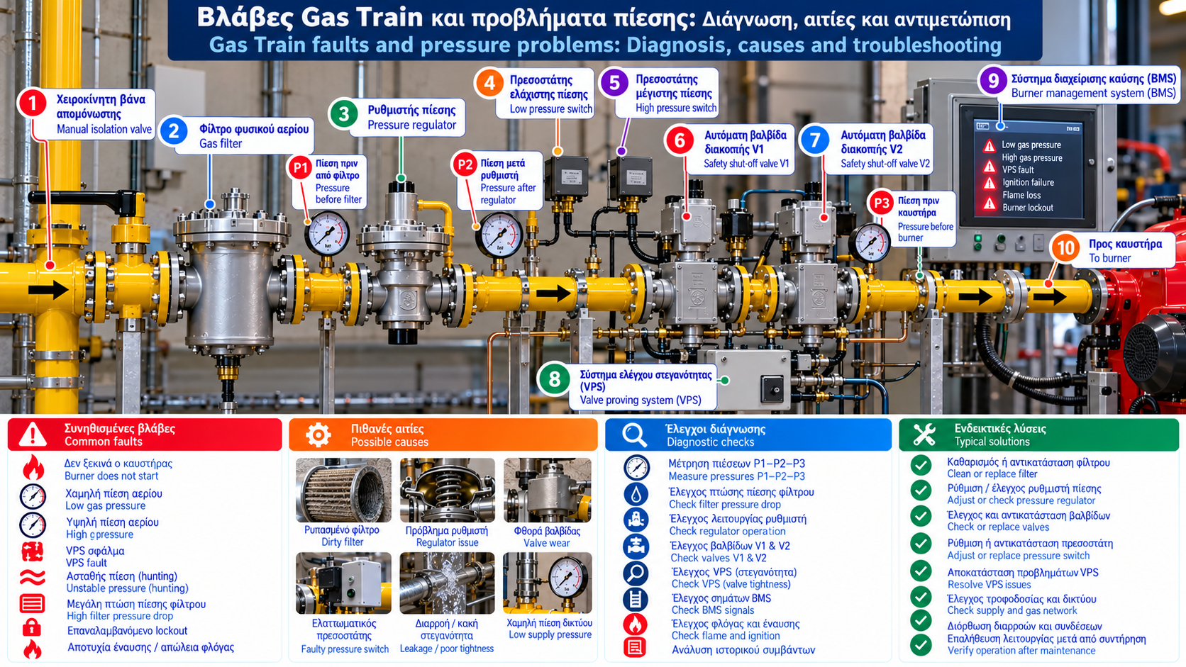
Gas Train Faults and Pressure Problems: Diagnosis, Causes and Troubleshooting
A gas train is a critical part of an industrial natural gas burner’s fuel supply and safety system.
When a fault occurs, the cause is not necessarily located inside the burner. It may involve network pressure, the gas filter, pressure regulator, pressure switches, automatic shut-off valves or the Burner Management System (BMS).
Effective troubleshooting requires systematic symptom evaluation, recording of actual operating conditions and verification of protective functions.
Safety note: All testing and intervention on gas installations must be performed by competent, authorized personnel. Pressure switches, valve proving systems, shut-off valves and other safety devices must never be bypassed.
1. What Are the Most Common Gas Train Problems?
Common symptoms include:
Burner failure to start.
Low gas pressure trips.
High gas pressure trips.
Valve Proving System (VPS) failures.
Unstable gas pressure.
Reduced burner capacity at high load.
Repeated burner lockouts.
Ignition failure or flame loss.
Each symptom can have several possible causes. Replacing components without a verified diagnosis may fail to resolve the underlying issue.
2. Burner Does Not Start: Possible Causes
When a burner fails to start, first identify the stage at which the operating sequence stops.
Possible issues include:
A required safety condition is not satisfied.
Gas pressure is outside permissible limits.
The VPS test fails.
A protective lockout is active.
The required pre-purge sequence is incomplete.
Ignition or flame confirmation fails.
The burner controller’s fault indication and event history are usually the first sources of diagnostic information.
A start command displayed on SCADA does not prove that all required safety prerequisites have been satisfied.
3. Low Natural Gas Pressure
Low pressure is a common operating problem.
Possible causes include:
Insufficient gas network pressure.
Excessive pipeline pressure losses.
Contaminated gas filter.
Insufficient regulator capacity.
Excessive simultaneous gas demand.
Incorrect component sizing.
Troubleshooting must distinguish static pressure from pressure under actual operating load.
An installation may show acceptable pressure when the burner is stopped but experience a significant pressure reduction as gas demand increases.
4. Where Should Gas Pressure Be Measured?
Assessment should use the installation’s designated pressure measurement points.
Useful locations may include:
P1: Upstream of the gas filter.
P2: Downstream of the gas filter.
P3: Upstream of the regulator.
P4: Downstream of the regulator.
P5: At a designated burner supply point.
These locations are illustrative. Actual component order and measurement arrangements may differ.
Pressure readings should be correlated with gas flow, burner operating stage and equipment performance data.
5. Gas Filter Pressure Drop
As a gas filter collects contaminants, its resistance to flow may increase.
Filter differential pressure is:
ΔPfilter = Pupstream − Pdownstream
For example:
Upstream pressure: 180 mbar.
Downstream pressure: 165 mbar.
Therefore:
ΔP = 15 mbar
This value alone does not prove that the filter must be replaced.
It must be assessed against operating flow, manufacturer specifications and previous measurements.
6. Pressure Drop at High Burner Load
A burner may operate normally at low firing rate but develop problems as load increases.
Possible causes include:
Insufficient network capacity.
Excessive pressure losses.
Undersized regulator.
Restrictions in filters or valves.
Unacceptable regulator pressure droop.
Assessment must be performed under actual operating conditions without bypassing protective devices to achieve higher load.
7. Unstable Regulator Outlet Pressure
Unstable pressure may appear as repeated oscillation around the required setpoint.
This behavior is known as regulator hunting.
Possible causes include:
Incorrect sizing.
Interaction between regulators.
Unfavorable flow variations.
Pressure sensing line problems.
Mechanical wear.
Unsuitable installation conditions.
Diagnosis requires recording pressure over time and evaluating the system’s dynamic response.
Arbitrary spring adjustments are not an acceptable troubleshooting method.
8. Excessive Pressure Downstream of the Regulator
High downstream pressure may be associated with:
Incorrect adjustment.
Valve seat failure.
Lock-up problems.
Regulating mechanism failure.
Problems in an upstream pressure regulation stage.
Normal lock-up behavior within specifications must be distinguished from uncontrolled pressure rise.
Downstream protection must be evaluated against the installation’s overpressure safeguards.
Resetting a high-pressure trip without investigating the cause is not a solution.
9. Low Gas Pressure Switch Fault
A Low Gas Pressure indication may mean:
Actual gas pressure is below the acceptable limit.
The sensing device or associated circuit has a fault.
Distinguishing these possibilities requires suitable pressure verification and evaluation of the safety circuit.
A pressure switch should not be considered defective simply because it prevents burner startup.
10. High Gas Pressure Switch Fault
A high-pressure trip may result from actual overpressure or a problem with the sensing device.
Assessment includes:
Reviewing recorded operating conditions.
Verifying pressure using a suitable instrument.
Evaluating regulator operation.
Checking related protective devices.
Trip thresholds must not be altered merely to avoid recurring shutdowns.
11. What Does VPS Fault Mean?
A VPS Fault indicates that the valve proving system did not successfully complete its required test.
Possible causes include:
Unacceptable automatic valve tightness.
Pressure sensing problems.
Unsuitable supply pressure.
Electrical or electronic faults.
Conditions incompatible with the proving procedure.
The VPS must not be bypassed.
Diagnosis should follow the fault code and manufacturer’s approved procedures.
12. Automatic Gas Valve Problems
Automatic safety shut-off valves may develop electrical, mechanical or operating problems.
Possible symptoms include:
Failure to complete startup.
VPS test failure.
Disagreement between valve command and position feedback, where available.
Protective shutdown.
An opening command does not prove that a valve has physically opened.
Similarly, the absence of an opening command does not independently confirm gas-tight closure.
Required tests must be performed by qualified personnel.
13. Why Does Repeated Burner Lockout Occur?
Burner lockout is a protective condition that prevents operation after certain faults.
Repeated lockouts may involve:
Ignition failure.
Flame loss.
Gas pressure problems.
Valve proving failure.
Unsatisfied safety interlocks.
Combustion air supervision problems.
Recording the exact fault code and event time is essential.
Repeated resets without identifying the cause can create serious hazards.
14. How Can SCADA Help Troubleshooting?
A properly configured SCADA system can support fault analysis through historical data.
Useful signals include:
Gas train inlet pressure.
Regulator outlet pressure.
Pressure switch status.
VPS status.
Valve commands.
Valve position feedback, where available.
Flame detection.
Burner load.
Fault code and timestamp.
Correlating pressure trends with burner load is particularly valuable.
SCADA supports monitoring and diagnosis but does not replace certified combustion safety functions.
15. Example: Diagnosing a Pressure Drop
Consider a hypothetical gas train.
At low load:
Pressure upstream of filter: 200 mbar.
Pressure downstream of filter: 198 mbar.
Regulator outlet pressure: 100 mbar.
At high load:
Pressure upstream of filter: 185 mbar.
Pressure downstream of filter: 170 mbar.
Regulator outlet pressure: 82 mbar.
Observations:
Supply pressure decreases under load.
Filter differential pressure increases from 2 to 15 mbar.
Regulator outlet pressure decreases from 100 to 82 mbar.
These results suggest evaluating supply capacity, filter resistance and regulator performance.
They do not independently establish a definitive fault.
Actual gas flow, equipment performance curves and specified operating conditions are also required.
16. Quick Gas Train Troubleshooting Table
Symptom | Possible Cause | What to Assess |
Burner fails to start | Active safety condition | BMS code and startup prerequisites |
Low gas pressure | Insufficient supply | Loaded pressure readings |
High filter pressure drop | Contamination or restriction | Differential pressure and flow |
Pressure falls at high load | Insufficient system capacity | Component performance curves |
Pressure oscillation | Hunting | Dynamic pressure recording |
High outlet pressure | Regulation or lock-up problem | Specifications and safeguards |
VPS Fault | Valve proving problem | VPS code and approved testing |
Frequent lockout | Repeated protective condition | Event history |
Ignition failure | Combustion sequence issue | BMS and flame supervision data |
17. A Practical Troubleshooting Method
A structured assessment can follow six stages.
Stage 1 — Record the symptom
Determine whether the fault occurs before startup, during ignition, at low load or at high load.
Stage 2 — Review event history
Examine fault codes and recorded events.
Stage 3 — Assess available measurements
Correlate pressure, flow and burner load.
Stage 4 — Compare with specifications
Verify whether operating conditions meet equipment limits.
Stage 5 — Perform specialist tests
Where required, competent personnel carry out approved tests.
Stage 6 — Document the results
Record findings, corrective actions and verification results.
18. Preventive Gas Train Maintenance
Preventive maintenance can reduce the likelihood of unplanned shutdowns.
A maintenance program may include:
Gas filter inspection.
Pressure recording under defined operating conditions.
Regulator performance assessment.
Required tightness testing.
Automatic valve checks.
VPS testing.
Pressure switch verification.
Safety interlock checks.
BMS event history review.
Inspection intervals depend on manufacturer instructions, installation criticality and applicable requirements.
19. Relevant Technical Standards
Depending on the equipment and application, relevant references include:
EN 676: Automatic forced draught burners for gaseous fuels.
EN 88-1: Pressure regulators and associated safety devices for gas appliances.
EN 161: Automatic shut-off valves for gas burners and appliances.
EN 1643: Valve proving systems for automatic shut-off valves.
EN 1854: Pressure sensing devices for gas burners and appliances.
EN 298: Automatic burner control systems.
EN 334: Gas pressure regulators within the standard’s scope.
The applicable editions and requirements must be verified for the specific installation.
Conclusion
Gas train troubleshooting requires a systematic approach rather than random adjustments or component replacement.
Loaded pressure measurements, filter differential pressure, regulator performance curves and BMS data provide valuable diagnostic evidence.
Safe troubleshooting depends on identifying the actual cause, following approved procedures and verifying correct operation before returning the installation to service.