
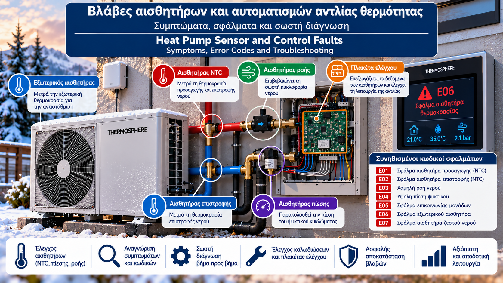
Heat Pump Sensor and Control Faults: Symptoms, Error Codes and Troubleshooting
Modern heat pumps use multiple sensors and electronic control systems to monitor temperature, pressure, water flow and compressor operation.
These sensors send information to the main controller, which determines when the heat pump should operate, how its output should change and when protective functions must be activated.
When a sensor fails or provides incorrect measurements, the heat pump may display an error code, limit its heating output or shut down.
However, a sensor-related error code does not always mean the sensor itself needs replacing.
The actual cause may be damaged wiring, a loose connector, a genuine system fault or an electronic controller problem.
This guide explains the main types of sensor and control faults, common symptoms and the correct approach to diagnosis.
1. Why Are Sensors Important in Heat Pumps?
Sensors are essential components of a heat pump’s control system.
They monitor parameters such as:
Outdoor temperature.
Heating-water flow temperature.
Heating-water return temperature.
Heat exchanger temperatures.
Refrigerant circuit temperatures.
Refrigerant pressure.
Water flow.
Water pressure, where a suitable sensor is fitted.
Room or domestic hot water cylinder temperature.
The controller uses these measurements to keep the system within permitted operating limits.
Not all heat pumps use the same sensors or control strategies.
2. What Are the Main Symptoms of a Sensor Fault?
Possible symptoms include:
The heat pump fails to start.
Operation stops unexpectedly.
An error code appears.
A displayed temperature is unrealistic.
Water temperature does not match heating demand.
The heat pump starts and stops frequently.
Domestic hot water production becomes insufficient.
Unusual pressure or flow readings appear.
The controller loses communication with a component.
These symptoms do not automatically prove that a sensor has failed.
The actual operating conditions must also be checked.
3. What Is an NTC Sensor?
An NTC sensor is a thermistor whose electrical resistance decreases as temperature increases.
NTC thermistors are widely used to measure temperatures in heating systems.
They may be installed at:
Water flow pipes.
Water return pipes.
Outdoor air measurement points.
Heat exchangers.
Domestic hot water cylinders.
Selected refrigerant circuit locations.
Resistance characteristics vary between sensor types.
For example, two sensors described as NTC 10 kΩ are not necessarily interchangeable because their resistance–temperature curves may differ.
4. How Does an NTC Fault Appear?
Possible symptoms include:
Extremely high or low displayed temperatures.
Intermittent readings.
Open-circuit error codes.
Short-circuit error codes.
Incorrect control decisions.
Protective shutdowns.
For example, if the flow temperature sensor reports an unrealistic value, the controller may reduce or stop heating operation.
However, the exact electrical fault cannot always be identified from the displayed temperature alone.
The response depends on the measurement circuit.
5. How Is a Temperature Sensor Tested?
A qualified technician should follow the manufacturer’s diagnostic procedure.
This may include:
Reading the error code.
Checking the actual temperature.
Comparing it with the controller display.
Inspecting connectors and wiring.
Measuring sensor resistance where specified.
Comparing measurements with the official resistance–temperature table.
Checking the corresponding control board input.
Electrical measurements must follow the appropriate isolation and safety procedures.
Protective sensors must never be bypassed or bridged without an approved manufacturer procedure.
6. Outdoor Temperature Sensor Faults
The outdoor temperature sensor is often used for weather compensation.
Incorrect readings may cause the heat pump to calculate an unsuitable heating-water flow temperature.
Possible symptoms include:
Rooms overheating.
Insufficient heating.
Unrealistic outdoor temperature readings.
Unstable weather compensation.
Related error codes.
Before replacing the sensor, technicians should consider whether its position, direct sunlight or nearby heat sources are affecting the reading.
7. Flow and Return Temperature Sensor Faults
Flow and return sensors monitor temperatures within the heating-water circuit.
Depending on the model, the controller may use the difference between these readings for operational monitoring or protective functions.
Possible symptoms include:
An unusual flow-to-return temperature difference.
Failure to achieve the target flow temperature.
Water temperature errors.
Operating interruptions.
Unexpected protective shutdowns.
An abnormal temperature difference may also indicate genuinely insufficient water flow.
It should not automatically be attributed to a faulty sensor.
8. What Is a Flow Sensor or Flow Switch?
Water flow monitoring devices confirm that water is circulating through the system.
Depending on the design, a heat pump may use:
A flow switch.
A quantitative water flow sensor.
Another circulation verification device.
A flow switch may confirm whether water flow exceeds a defined threshold.
A quantitative flow sensor may report an actual flow rate, such as litres per minute.
These devices are not necessarily interchangeable.
9. Why Does a Low-Flow Error Occur?
Possible causes include:
Closed isolation valves.
Blocked strainers or filters.
Air trapped in the circuit.
Circulation pump problems.
Closed heating zone valves.
Poor hydraulic balancing.
Genuinely insufficient water flow.
Sensor or wiring faults.
A low-flow error does not necessarily mean the flow sensor must be replaced.
The required water circulation should first be verified.
10. What Happens When a Pressure Sensor Fails?
Some heat pumps use electronic pressure sensors in the refrigeration circuit or hydraulic circuit.
These sensors perform different functions.
In the refrigeration circuit, pressure relates to refrigerant operating conditions.
In the hydraulic circuit, pressure relates to the condition and operation of the water system.
Possible symptoms include:
Unrealistic pressure readings.
Sensor-related error codes.
Protective shutdowns.
Disagreement between displayed and independently measured pressure.
A high-pressure or low-pressure error may indicate a real operating problem rather than sensor failure.
Refrigerant circuit work must be performed only by appropriately qualified and certified personnel.
11. How Can a Real Fault Be Distinguished From an Incorrect Reading?
Diagnosis involves comparing the controller reading with reliable independent information.
For example:
An outdoor sensor displays 35°C during freezing weather.
A displayed pressure does not match a valid independent measurement.
The controller reports zero water flow even though circulation has been independently confirmed.
Such situations may indicate a sensor, connection or control board input problem.
However, when independent measurements confirm the displayed value, the underlying operating fault must be investigated.
12. Refrigerant Circuit Sensor Faults
The refrigerant circuit may contain temperature and pressure sensors at several locations.
Depending on the system, their readings may be used for:
Compressor control.
Discharge temperature monitoring.
Electronic expansion valve management.
Defrost control.
Protection against unsafe operating conditions.
A sensor fault may cause reduced output or a protective shutdown.
Diagnosis requires specialist equipment and knowledge of the specific refrigeration system.
13. Why Do Communication Errors Occur?
A heat pump may contain several electronic control modules.
Examples include:
Main control board.
Inverter board.
Indoor unit controller.
Outdoor unit controller.
User interface.
Communication module.
These components exchange information through cables or communication interfaces.
Possible causes of communication faults include:
Broken wiring.
Loose connectors.
Incorrect power supply.
Electromagnetic interference.
Incorrect configuration.
Electronic module failure.
A communication error code does not automatically prove that a circuit board has failed.
14. What Is a Control Board Fault?
The control board processes sensor readings and manages system functions.
A fault may affect:
Sensor measurements.
Communication.
Output activation.
Power supplied to peripheral components.
Execution of operating commands.
However, an incorrect reading does not justify immediate board replacement.
Sensors, wiring, connectors and power supply should first be checked.
Replacing a control board without a confirmed diagnosis can lead to unnecessary expense.
15. Thermostat Fault or Heat Pump Fault?
When a heat pump does not start, the problem may involve heating demand rather than the heat pump itself.
For example:
The thermostat is not requesting heating.
The temperature setpoint is too low.
A time schedule is active.
A central controller is preventing demand.
Wiring is faulty.
The heat pump is in a protective state.
Diagnosis should confirm whether the heating demand reaches the controller and whether operation is permitted.
Electrical contacts must not be bridged arbitrarily.
16. What Do Heat Pump Error Codes Mean?
Error codes provide diagnostic information through the controller display.
They may relate to:
Temperature sensors.
Low water flow.
Refrigerant pressure.
Hydraulic pressure.
Communication between modules.
Circulation pumps.
Compressors.
Electronic control boards.
Defrost.
Frost protection.
There is no universal heat pump error code table covering every manufacturer and model.
The same number or letter combination may indicate different faults on different heat pumps.
Reliable interpretation requires the brand, exact model and relevant technical manual.
17. Why Should You Avoid Repeated Resets?
Resetting a fault may allow the heat pump to restart if the problem has been corrected and the manufacturer permits the action.
However, repeated resets without diagnosis are not a solution.
They may:
Conceal a recurring problem.
Make fault conditions harder to document.
Cause repeated protective shutdowns.
Delay repair of a genuine malfunction.
The error code should be recorded before any reset, and manufacturer instructions must be followed.
18. How Should a Systematic Diagnosis Be Performed?
A structured technical diagnosis may follow these stages.
Stage 1: Record Symptoms
Record the error code, time, outdoor temperature and operating condition.
Stage 2: Identify the Equipment
Confirm the brand, model and controller version.
Stage 3: Consult Technical Documentation
Locate the official error description.
Stage 4: Verify Actual Operating Conditions
Check relevant temperatures, pressures and water flow.
Stage 5: Test Sensors and Wiring
Qualified personnel perform the specified measurements.
Stage 6: Check the Controller
Confirm that inputs are being interpreted correctly and related circuits operate as intended.
Stage 7: Repair and Verify
After corrective work, confirm proper operation under suitable conditions.
19. Common Symptoms and Possible Causes
Symptom | Possible causes |
Unrealistic temperature reading | Sensor, wiring, connector, board input |
Low-flow error | Filter, valves, air, pump, sensor |
High-pressure error | Refrigeration operating conditions, sensor or control |
Communication error | Wiring, power supply, configuration, control board |
Heat pump does not start | No heating demand, protection, sensor, power supply |
Frequent shutdowns | Flow, heating load, settings, protective functions |
Incorrect weather compensation | Outdoor sensor, sensor placement, settings |
Insufficient domestic hot water | Cylinder sensor, schedule, valve, actual heating output |
This table is intended for initial investigation rather than definitive diagnosis.
20. What Can Homeowners Check Safely?
Homeowners can perform basic checks without opening electrical enclosures or accessing the refrigeration circuit.
Useful actions include:
Record the error code.
Photograph the controller display.
Check the desired temperature.
Review operating schedules.
Check whether a power outage has occurred.
Look for obvious external water leaks.
Note whether the problem occurs under particular conditions.
Provide this information to the service technician.
Homeowners should not open electrical panels, bypass safety devices or work on refrigerant pipework.
21. When Should Operation Be Stopped?
Immediate technical assessment is required if there are signs such as:
A burning smell.
Smoke.
Visible electrical damage.
Serious water leakage near electrical components.
Repeated protective trips.
Unusually loud mechanical noise.
Suspected refrigerant leakage.
If safe, follow the prescribed shutdown procedure and contact a qualified technician.
If a flammable refrigerant such as R290 is suspected of leaking, avoid ignition sources and follow the manufacturer’s safety instructions.
22. How Can Sensor and Control Faults Be Prevented?
Preventive maintenance may include:
Reviewing recorded error history.
Inspecting wiring and connectors.
Checking sensor operation.
Inspecting water filters.
Confirming adequate circulation.
Checking circulation pumps.
Testing zone valves.
Verifying weather compensation settings.
Reviewing available software updates.
Confirming protective functions.
Maintenance should follow the manufacturer’s schedule.
Preventive work cannot eliminate every possible fault, but it can help identify developing problems earlier.
23. Frequently Asked Questions
How Do I Know if a Heat Pump Sensor Has Failed?
Possible signs include unrealistic temperature readings, sensor error codes and unexpected shutdowns. Confirmation requires technical testing.
What Does an NTC Error Mean?
It usually indicates a temperature measurement problem or a fault in the associated electrical circuit. Exact interpretation depends on the manufacturer.
Can a Faulty Sensor Increase Electricity Consumption?
Yes, if incorrect measurements affect operation. In other cases, the heat pump may shut down for protection.
Why Is There a Flow Error When the Circulation Pump Is Running?
A running pump does not guarantee adequate water flow. Restrictions, trapped air, closed valves or sensor faults may still be present.
Can I Replace an NTC Sensor Myself?
This is not recommended without appropriate technical knowledge and manufacturer instructions. Correct replacement parts and safe procedures are essential.
Are Heat Pump Error Codes the Same Across All Brands?
No. Manufacturers and model ranges may use different codes.
Why Does a Communication Error Appear?
Possible causes include wiring, power supply, connectors, configuration or electronic module problems.
Can I Reset the Heat Pump to Restore Heating?
Only if the manual permits it and there are no signs of danger. Recurring errors require proper diagnosis.
When Does a Control Board Need Replacing?
When testing confirms that the board is faulty after checking associated components, connections and power supply.
What Information Does a Technician Need?
The brand, model, exact error code, a photograph of the display, when the fault appeared and the operating conditions.
Conclusion
Sensors and electronic controls are essential to the safe and efficient operation of a heat pump.
Incorrect measurements can affect space heating, domestic hot water production, weather compensation and protective functions.
However, correct troubleshooting cannot rely on an error code alone.
It requires technical documentation, actual measurements, wiring checks and an assessment of operating conditions.
Identifying the true cause is more important than immediately replacing a component.
Systematic diagnosis reduces unnecessary repairs and supports reliable system operation.
Thermosphere.gr — Technical knowledge for heating and building systems.