
# Industrial Automation: PLCs, Sensors and Fundamental Operating Principles
## Introduction
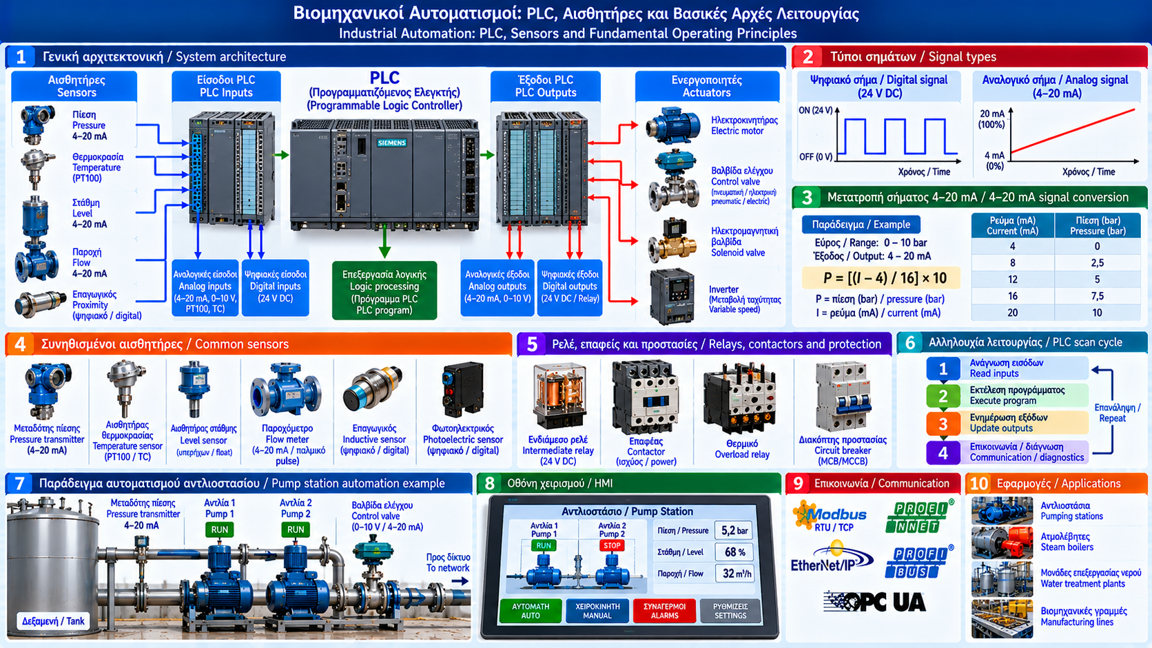
Industrial automation is a fundamental part of modern industrial operations. It enables machines and processes to be monitored, controlled and regulated with limited continuous human intervention.
Pumping stations, steam boilers, burners, water treatment plants, manufacturing lines and material handling systems rely on automation for consistent and safe operation.
An automation system combines sensors, programmable controllers, electrical circuits, actuators and operator interfaces.
Understanding these components is essential for both operation and troubleshooting.
## 1. What Is Industrial Automation?
Industrial automation uses control systems to perform tasks with reduced need for continuous manual intervention.
An automation system can:
- Start and stop machines.
- Monitor pressure, temperature and level.
- Adjust motor speed.
- Control valves.
- Monitor operating conditions.
- Generate alarms.
- Record data.
- Execute predefined sequences.
Its operation depends on field information and programmed control logic.
## 2. Main Components of an Automation System
A typical system includes:
1. Sensors and measuring instruments.
2. Input modules.
3. A PLC or another controller.
4. Output modules.
5. Relays, contactors and power drives.
6. Actuators and final equipment.
7. Operator interfaces or supervisory systems.
The basic information flow is:
Sensor → PLC input → Logic processing → PLC output → Actuator → Physical process.
The process affects the measured variables, creating a continuous monitoring and control cycle.
## 3. What Is a PLC?
PLC stands for Programmable Logic Controller.
It is an industrial controller designed for reliable operation in demanding environments.
A PLC can:
- Read digital inputs.
- Read analog inputs.
- Execute programmed logic.
- Control digital outputs.
- Generate analog control signals.
- Communicate with other devices.
- Manage alarms and sequences.
A PLC is not necessarily the only controller in a facility. Depending on the application, it may work alongside standalone controllers, DCS platforms or safety systems.
## 4. How Does a PLC Scan Cycle Work?
Many PLCs execute a repeating operating cycle.
In a simplified typical sequence:
1. Read inputs.
2. Execute the program.
3. Update outputs.
4. Perform communication and diagnostic tasks.
5. Repeat.
Actual execution depends on controller architecture and configuration.
Some PLCs support interrupts, periodic tasks with different priorities and direct input/output access.
Therefore, not every PLC follows exactly the same scan sequence.
## 5. Digital Inputs
Digital inputs represent two-state signals.
Examples include:
- Start pushbuttons.
- Stop pushbuttons.
- Limit switches.
- Motor overload contacts.
- Pressure switch contacts.
- Valve position feedback.
- Contactor auxiliary contacts.
Many industrial systems use 24 V DC signals.
However, voltage ratings and activation logic depend on equipment specifications.
A digital input can represent ON or OFF without ON necessarily indicating a normal condition.
## 6. Digital Outputs
Digital outputs provide commands to activate or deactivate devices.
Examples include:
- Intermediate relays.
- Contactor coils through suitable circuits.
- Solenoid valves.
- Indicator lamps.
- Alarm sounders.
PLC outputs may use transistor, relay or other technologies.
Electrical ratings, protective devices and load compatibility must always be verified.
A PLC output should never be assumed capable of driving any load directly.
## 7. Analog Inputs
Analog inputs represent variables that can take multiple values.
Examples include:
- Pressure.
- Temperature.
- Level.
- Flow.
- Valve position.
- Concentration of selected substances.
Common industrial signals include:
- 4–20 mA.
- 0–10 V.
- Other voltage or current ranges, depending on equipment.
RTDs and thermocouples can also be connected through suitable input modules or transmitters.
## 8. Example: Converting a 4–20 mA Signal
Consider a pressure transmitter configured for 0–10 bar with a 4–20 mA output.
Linear scaling is:
P = [(I − 4) / 16] × 10
where:
P = pressure in bar.
I = current in mA.
At I = 12 mA:
P = [(12 − 4) / 16] × 10.
P = 5 bar.
Therefore, 12 mA represents 5 bar in this example.
The equation applies to a linearly configured transmitter with these specific limits.
A 4 mA signal represents the lower measurement limit and does not automatically indicate a fault.
## 9. Why Is 4–20 mA Widely Used?
The 4–20 mA signal offers practical advantages in industrial installations.
These include:
- Analog information transmission.
- Suitability for many long cable runs within specified limits.
- Reduced sensitivity to cable voltage drop compared with certain voltage-based arrangements.
- Ability to distinguish the lower measurement limit from some open-circuit conditions.
Very low or high current values may indicate faults, depending on configuration and applicable standards.
Not every out-of-range current has the same meaning.
## 10. Industrial Sensors
Sensors convert physical conditions into information used by the control system.
Common types include:
### Pressure Sensors
Measure liquid or gas pressure.
### Temperature Sensors
Use technologies such as Pt100, Pt1000, thermocouples or electronic transmitters.
### Level Sensors
Monitor liquid level in tanks and vessels.
### Flow Sensors
Measure liquid or gas flow.
### Inductive Sensors
Detect suitable metallic objects without physical contact.
### Photoelectric Sensors
Use light to detect objects or position changes.
Sensor selection depends on range, accuracy, environment and process requirements.
## 11. Relays and Contactors
Relays switch electrical circuits.
Contactors are commonly used to control power loads such as electric motors.
A typical motor starter may include:
- PLC.
- Intermediate relay where required.
- Contactor.
- Overload protection.
- Protective circuit breaker.
- Permissive circuitry.
- Electric motor.
The PLC provides a control command, while suitable power components switch the electrical load.
Protection must operate according to the electrical design and safety requirements.
## 12. Actuators
Actuators convert control commands into physical action or movement.
Examples include:
- Solenoid valves.
- Pneumatic actuators.
- Electric valve actuators.
- Electric motors.
- Variable-speed drives.
- Hydraulic actuators.
An actuator may operate through ON/OFF commands or continuous modulation.
Selection depends on force, speed, accuracy and safety requirements.
## 13. Open-Loop and Closed-Loop Control
### Open-Loop Control
The system executes a command without continuously using feedback of the controlled variable to correct its action.
Example:
A motor operates for a predetermined time.
### Closed-Loop Control
The system compares a measured value with a target value and adjusts the output.
Example:
A pressure transmitter measures network pressure, and a controller adjusts pump speed to maintain the desired pressure.
Feedback allows the system to respond to load and operating condition changes.
## 14. What Is PID Control?
PID is a widely used control algorithm.
It consists of:
- Proportional action.
- Integral action.
- Derivative action.
The controller calculates its action using the difference between the desired and measured values.
Applications include:
- Pressure control.
- Temperature control.
- Level control.
- Flow control.
PID tuning must reflect process dynamics.
Incorrect settings may cause oscillation, slow response or instability.
## 15. Pumping Station Automation Example
Consider a pumping station with two pumps and a pressure transmitter.
The PLC receives:
- Network pressure.
- Motor status.
- Protection signals.
- Operating permissives.
- Operator commands.
The program may:
1. Verify start permissives.
2. Start the first pump.
3. Adjust speed through a variable-frequency drive when installed.
4. Start the second pump when required and permitted.
5. Alternate lead pump selection.
6. Stop equipment under defined conditions.
7. Record alarms.
The exact logic must reflect hydraulic requirements, protective functions and equipment specifications.
## 16. Steam Boiler Automation Example
Industrial steam boilers use control systems for:
- Pressure monitoring.
- Water level control.
- Feedwater regulation.
- Load adjustment.
- Operating status records.
- Alarm indication.
Critical safety functions, including required low-water, overpressure and burner safeguards, must be implemented using suitable certified systems in accordance with applicable standards.
An ordinary process-control PLC must not automatically be considered suitable for every safety function.
## 17. Interlocks and Permissives
Interlocks are logic functions or devices that prevent or interrupt an action when defined conditions are not satisfied.
Permissives are conditions that must be met before an action can proceed.
A pump start sequence may require:
- Available electrical supply.
- No active protection preventing startup.
- Adequate suction level.
- Suitable valve status.
- A valid run command.
Required conditions differ between installations.
Safety interlocks must not be bypassed without an approved procedure and appropriate risk assessment.
## 18. HMI and SCADA
HMI stands for Human Machine Interface.
It allows operators to monitor and control equipment.
SCADA stands for Supervisory Control and Data Acquisition.
It supports supervision, data collection and management of larger systems.
Typical functions include:
- Displaying measurements.
- Showing equipment status.
- Recording alarms.
- Displaying trends.
- Adjusting authorized settings.
- Maintaining operating history.
HMI and SCADA do not replace independent safety protections.
## 19. Industrial Communication
PLCs communicate with other devices through industrial networks.
Examples include:
- Modbus RTU.
- Modbus TCP.
- PROFINET.
- EtherNet/IP.
- PROFIBUS.
- OPC UA.
These technologies differ in architecture, functionality and implementation requirements.
Selection depends on equipment compatibility, data exchange requirements and overall system architecture.
## 20. Common Automation Faults
Automation problems are not always caused by the PLC itself.
Common causes include:
- Failed sensors.
- Broken wires.
- Loose terminals.
- 24 V DC supply problems.
- Faulty relays.
- Contactor failures.
- Input/output module faults.
- Communication loss.
- Incorrect configuration.
- Active process protection.
Effective diagnosis requires examination of both electrical circuits and control logic.
## 21. Basic Troubleshooting Procedure
A structured approach includes:
1. Recording symptoms and alarms.
2. Establishing safe working conditions.
3. Verifying power supply status.
4. Checking PLC and I/O indicators.
5. Inspecting sensors and wiring.
6. Confirming actual process conditions.
7. Reviewing logic and permissives.
8. Checking output circuits and actuators.
9. Implementing approved corrective action.
10. Testing and recording results.
Electrical measurements and interventions must be performed by suitably trained and authorized personnel.
## 22. Safety and Cybersecurity
Industrial automation directly affects physical equipment.
Important requirements include:
- Proper electrical design.
- Suitable protective devices.
- Separation of process control from required safety functions.
- Approved change management.
- Program backups.
- Access control.
- Industrial network protection.
- Safe equipment isolation procedures.
The IEC 62443 series provides an important reference framework for cybersecurity in industrial automation and control systems.
## Conclusion
Industrial automation combines sensors, PLCs, electrical circuits, actuators and supervisory systems to monitor and control processes.
Understanding digital and analog signals, interlocks, PLC logic and final equipment operation is essential for reliable operation and effective troubleshooting.
Proper design, documentation and systematic maintenance improve industrial plant availability and safety.
Thermosphere.gr – Technical Knowledge for Professionals.