
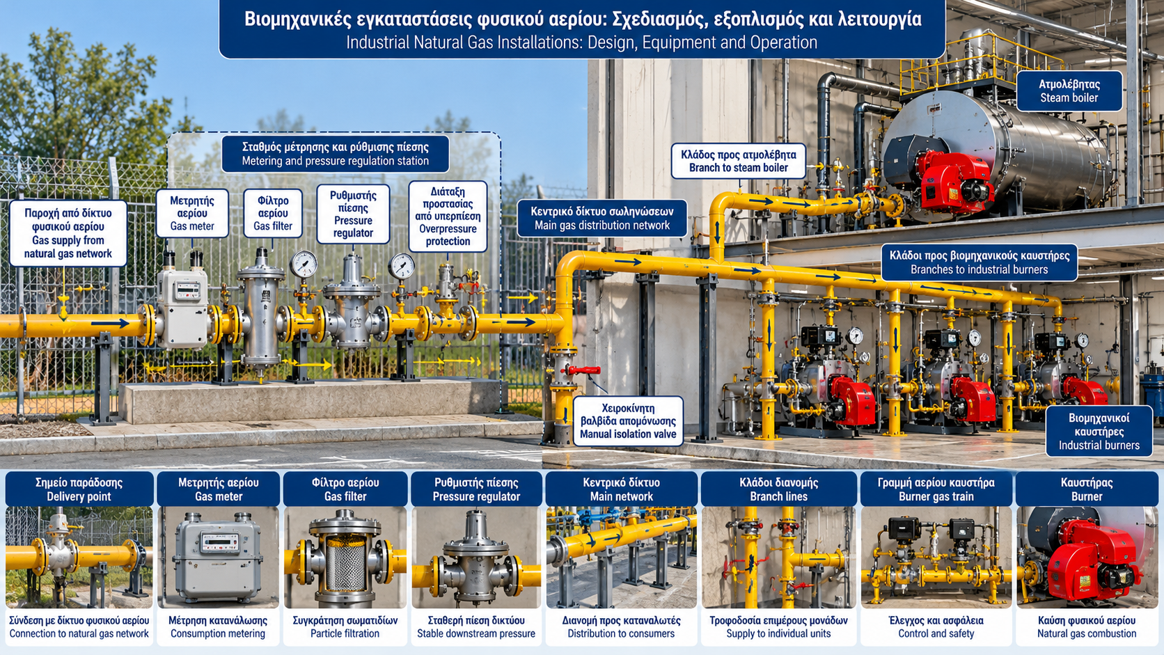
Industrial Natural Gas Installations: Design, Equipment and Operation
Industrial natural gas installations provide fuel to boilers, steam generators, burners and thermal process equipment.
Unlike small heating systems, industrial gas networks may supply multiple consumers with different operating pressures, flow requirements and load profiles.
Proper engineering involves more than selecting pipe diameters. It requires reliable gas distribution, pressure management, suitable isolation, safety protection and compliance with applicable technical requirements.
1. What Does an Industrial Gas Installation Include?
An industrial natural gas installation may include:
Gas delivery point.
Metering and pressure regulation equipment.
Main gas distribution piping.
Branches supplying individual consumers.
Manual isolation valves.
Overpressure protection equipment.
Monitoring and detection systems where required.
Individual burner gas trains.
Control and safety shutdown systems.
The actual arrangement depends on supply pressure, installed capacity, the number of consumers and site-specific requirements.
2. From Gas Delivery to the Burner
Gas enters the installation through the designated delivery point.
Metering, regulation and protective equipment may be installed according to the supply arrangement.
The internal piping network distributes gas to individual consumers.
Each consumer must receive gas at the pressure and flow rate specified for its equipment.
The final burner gas train provides the necessary control and safety shut-off functions.
Solenoid valves, pressure switches and burner gas trains are covered in separate Thermosphere.gr technical articles.
3. Calculating Natural Gas Demand
Determining the required gas flow is one of the first engineering tasks.
Fuel demand depends on the thermal input rating and the heating value of the gas.
The basic relationship is:
Gas flow = Fuel thermal input / Heating value per unit volume
For example, a burner with a thermal input of 1,000 kW supplied with gas having an LHV of 10 kWh/Nm³ would require approximately:
1,000 / 10 = 100 Nm³/h
This is an illustrative calculation rather than a universal natural gas specification.
The reference temperature and pressure defining the normal cubic meter must also be specified.
If the available rating represents useful boiler output rather than fuel input, boiler efficiency must first be considered.
4. Simultaneous Operation of Multiple Consumers
Industrial gas networks may supply several boilers or process burners operating at the same time.
The design flow must reflect realistic operating scenarios.
Important considerations include maximum individual consumption, simultaneous demand, production schedules, startup conditions, future expansion and gas supply limitations.
A diversity factor should only be applied when justified by the actual process requirements.
5. Gas Pipe Sizing
Correct pipe sizing is essential for reliable gas delivery.
Undersized piping can produce excessive pressure losses, especially at high flow rates.
Sizing calculations depend on gas flow, operating pressure, pipe length, local resistance, gas properties, allowable pressure drop and consumer requirements.
Pipe diameters should not be selected solely using simplified velocity rules.
An appropriate hydraulic calculation is required for the actual pressure and flow conditions.
6. Pressure Drop in Gas Networks
Gas flow through pipes generates pressure losses due to friction and local resistance.
Pressure losses increase with flow and depend on network geometry.
Particular attention should be given to long pipe runs, branches, bends, filters, regulating equipment and changes in pipe diameter.
The design must confirm that adequate pressure remains available at each consumer under the most demanding specified operating conditions.
7. Pressure Regulation and Overpressure Protection
The pressure available from the supply network may not be suitable for every consumer.
Pressure regulators are used to maintain downstream pressure within the required operating range.
Independent overpressure protection or other protective devices may also be required.
Selection must account for normal operating conditions and foreseeable equipment failures.
A pressure regulator should not be treated as a substitute for an independent safety function where one is required.
8. Materials and Pipework
Gas piping materials must be compatible with natural gas and the installation’s operating conditions.
Selection depends on design pressure, temperature, installation environment, corrosion exposure, mechanical loads and applicable standards.
Suitable metallic piping is commonly used in industrial installations, although permitted materials depend on the specific application.
Jointing methods, supports and corrosion protection must be addressed in the engineering design.
9. Indoor and Outdoor Gas Networks
Pipe routing should support safety, inspection and maintenance.
Outdoor piping may be exposed to moisture, temperature variation, mechanical impact and corrosive environments.
Indoor piping requires evaluation of ventilation, room use and potential ignition sources.
Routing through enclosed spaces, shafts or other special locations must follow the applicable technical requirements.
10. Isolation of Individual Branches
Industrial installations supplying multiple consumers require appropriate isolation arrangements.
The design should establish how a branch can be safely isolated for maintenance without creating uncontrolled conditions elsewhere in the network.
Valve accessibility and clear identification are important operational safety considerations.
11. Automation and Monitoring
Modern industrial installations may include monitoring of pressure, valve status, alarms and gas consumption.
Integration with BMS, PLC or SCADA systems can support:
Energy monitoring.
Alarm history.
Detection of abnormal pressure trends.
Preventive maintenance.
Operational analysis.
Safety functions, however, require appropriately designed equipment and the necessary independence. A general-purpose monitoring system does not automatically replace certified safety controls.
12. Commissioning and Initial Testing
Before a new installation enters service, specified inspections and tests must be completed.
Depending on the project, these may include:
Pipework and support inspection.
Verification of component suitability.
Required strength testing.
Tightness testing.
Verification of pressure regulation and protection.
Control and interlock checks.
Documentation and technical handover.
Test pressures, media and procedures must follow the applicable standards and approved design.
13. Installation Documentation
A properly managed industrial gas installation should have a suitable technical file.
Important records include:
Piping drawings and P&IDs.
Flow and pressure-drop calculations.
Equipment specifications.
Protective device settings.
Test certificates and reports.
Operation and maintenance instructions.
Modification and intervention records.
Documentation supports safe operation, maintenance and future modifications.
14. Standards and Regulations
Industrial natural gas installations must comply with the applicable national regulations and relevant technical standards.
Potential references include:
EN 15001-1: Design, materials, construction, inspection and testing requirements for gas installations within its scope.
EN 15001-2: Operational and maintenance requirements for corresponding installations.
EN 1775: Gas pipework for buildings, within its specified scope.
EN 12186: Gas pressure regulating stations, where applicable.
In Greece, the applicable technical regulation must be determined according to operating pressure, installation type and intended use.
A standard should not be assumed applicable to every industrial network without checking its scope.
Conclusion
An industrial natural gas installation is an integrated system for fuel transportation, distribution, regulation and safe delivery.
Reliable engineering requires accurate flow calculations, appropriate pipe sizing, suitable materials, pressure protection and complete technical documentation.
Installation safety and performance depend on the overall design rather than the quality of individual components alone.