
# Industrial Gas and Oil Burners: Types, Operation and Main Components
## Introduction
Industrial burners are essential equipment for generating thermal energy. They are used in steam boilers, hot-water boilers, thermal-oil heaters, industrial furnaces and other thermal processes.
Their purpose is to provide the appropriate fuel and combustion air, establish and maintain a stable flame, and safely match heat input to plant demand.
Gas and oil burners share fundamental combustion principles but differ significantly in fuel delivery, mixture preparation and associated equipment.
## 1. What Is an Industrial Burner?
An industrial burner is an assembly that introduces fuel and air into a combustion system to release heat under controlled conditions.
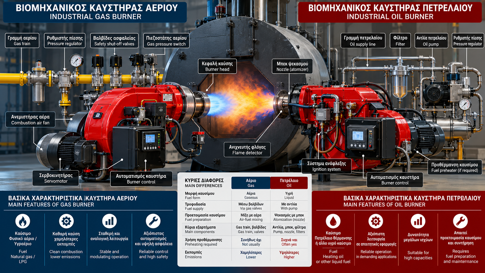
It typically includes a combustion-air fan, burner head, fuel delivery equipment, ignition system, flame supervision and burner controller.
Selection is not based on nominal firing capacity alone. Compatibility with furnace geometry, combustion-chamber backpressure, available fuel, required operating range and manufacturer specifications is essential.
## 2. Main Applications
Industrial burners are installed in steam-generation plants, industrial hot-water systems, thermal-oil systems, dryers, furnaces and material-processing equipment.
In a steam boiler, the burner provides heat transferred through boiler heating surfaces to generate steam at the required pressure.
In an industrial hot-water boiler, the objective is to maintain the required water temperature or another controlled process variable.
## 3. Industrial Gas Burners
Gas burners use natural gas, LPG or another suitable gaseous fuel when the equipment is approved and configured for that fuel.
Fuel passes through a gas train containing the required isolation, pressure-control, monitoring and automatic safety shutoff devices.
Gas is mixed with combustion air at an appropriate burner head. Ignition is initiated by an approved system, and flame presence is verified by a suitable detector.
Gas pressure, composition and heating value influence burner settings and available capacity.
## 4. Industrial Oil Burners
Oil burners use suitable liquid fuels, such as heating oil or other fuels specified by the equipment manufacturer.
Effective combustion requires the liquid fuel to be prepared and broken into fine droplets or introduced using another suitable combustion technology.
In common pressure-atomizing burners, a fuel pump and nozzle provide the required atomization.
Larger systems may use air-assisted or steam-assisted atomization. Certain heavier fuels require preheating and viscosity control.
## 5. Gas Versus Oil Burners
In gas burners, fuel arrives in gaseous form and its flow is managed by suitable valves and regulating devices.
In oil burners, pump performance, delivery pressure, filters, atomization quality and sometimes fuel temperature are especially important.
Both systems require adequate combustion air, reliable ignition, flame supervision and automatic fuel shutoff whenever required safety conditions are not met.
Fuel choice also affects maintenance, emissions, storage requirements and plant infrastructure.
## 6. Single-Stage Burners
A single-stage burner operates at one predefined firing rate whenever combustion is enabled.
Heat demand is met through burner start-and-stop cycles.
This is a relatively simple arrangement, but applications with frequently changing loads may experience more cycling.
Suitability depends on plant size and thermal-load behavior.
## 7. Two-Stage Burners
Two-stage burners provide two predefined firing rates, commonly low fire and high fire.
The control system selects the appropriate stage according to demand.
Oil burners may use suitable valves, nozzles or fuel-flow regulating arrangements to change firing rate.
Gas burners use corresponding approved gas-flow and air-control arrangements.
## 8. Modulating Burners
Modulating burners vary heat input continuously or in fine increments within a specified operating range.
Control may be based on steam pressure, water temperature or another process variable.
Modulation requires coordinated control of fuel and combustion air.
Modern systems may employ electronic fuel-air ratio control, servomotors and variable-frequency drives for the combustion-air fan.
Modulation alone does not guarantee high efficiency; proper commissioning and equipment sizing remain essential.
## 9. Combustion-Air Fan
The combustion-air fan supplies the airflow and pressure needed to overcome system resistance.
Airflow is influenced by damper position, fan speed, air density and combustion-chamber backpressure.
Insufficient air can produce incomplete combustion and elevated carbon monoxide. Excessive air can increase flue-gas heat losses.
Correct settings must be verified through appropriate combustion measurements.
## 10. Burner Head and Flame Stabilization
The burner head shapes fuel and air streams and helps stabilize the flame.
Its geometry affects flame shape, length and behavior.
Incorrect settings or burner-to-furnace incompatibility may cause instability, combustion pulsation or unwanted flame contact with heating surfaces.
Burner-head adjustments must follow manufacturer instructions.
## 11. Gas Train and Safety Equipment
A gas train may include a filter, pressure regulator, pressure switches, automatic safety shutoff valves and valve-tightness testing equipment.
The exact arrangement depends on burner design, capacity, application requirements and applicable standards.
Safety shutoff valves are not merely operating switches. They form part of the fuel safety shutdown system.
Bypassing pressure switches or supervision devices is not an acceptable troubleshooting method.
## 12. Oil Supply System
An oil supply system may include a storage tank, pipework, filters, pumps, valves and pressure-control devices.
Air entering the line, blocked filters or inadequate fuel delivery can interfere with atomization and ignition.
Return-line arrangements must comply with pump and installation specifications.
Leak inspection and fuel cleanliness are important reliability factors.
## 13. Oil Nozzles and Atomization
An oil nozzle converts liquid fuel into a spray of droplets whose characteristics depend on nozzle construction and operating conditions.
Important parameters include flow capacity, spray angle, spray pattern and operating pressure.
A worn or unsuitable nozzle can cause poor mixing, incomplete combustion and deposits.
Replacement must use the specified nozzle type, not simply one with a similar nominal flow rating.
## 14. Ignition System
Ignition uses a suitable arrangement, such as a high-voltage ignition transformer and electrodes or a separate pilot burner, depending on the design.
The ignition sequence is controlled by an approved burner controller.
Fuel admission is permitted only when the required conditions have been verified.
Ignition failure must produce the specified safe response, without arbitrary repeated restart attempts.
## 15. Flame Supervision
Flame supervision confirms an acceptable flame signal during the relevant operating phases.
Depending on the application, flame detection may use ionization, ultraviolet or other suitable technologies.
The detector must be compatible with the burner and its control system.
Loss of flame during operation must trigger the required safe fuel shutoff.
## 16. Burner Management System
The Burner Management System (BMS) manages critical burner safety sequences.
Depending on the installation, it supervises startup permissives, pre-purge, ignition, flame detection and safe shutdown.
The BMS must not be confused with a basic temperature or pressure controller.
Where PLCs are used, safety functions require suitably engineered and assessed systems; an ordinary PLC does not automatically constitute an adequate safety system.
## 17. Basic Startup Sequence
A typical sequence includes a call for heat, verification of permissives, pre-purge, positioning for ignition, activation of the specified ignition equipment and flame confirmation.
Following successful ignition, the burner transitions to its permitted normal operating state.
The exact sequence, timing and required checks vary with equipment and applicable standards.
A generic sequence must not be used as a commissioning procedure without manufacturer documentation.
## 18. Fuel-Air Ratio
Combustion requires sufficient oxygen to react with the fuel.
The theoretical or stoichiometric air requirement depends on fuel composition.
In practice, appropriate excess air is supplied to achieve stable, complete combustion within the operating limits of the installation.
The optimum setting cannot be defined by one universal O₂ value. It depends on burner design, fuel, firing rate and emissions requirements.
## 19. Flue-Gas Analysis
Flue-gas analysis supports combustion assessment and burner adjustment.
Common measurements include O₂, CO, flue-gas temperature and, where required, CO₂ and NOₓ.
Oil burners may additionally require smoke or soot assessment and other fuel-specific checks.
Measurements require suitable instruments, correct sampling practices and the specified operating conditions.
## 20. Efficiency and Energy Consumption
Thermal-system efficiency is influenced by combustion quality, flue-gas losses, boiler losses and load behavior.
Correct modulation can reduce unnecessary cycling and improve operational stability.
Using a VFD on the combustion-air fan may reduce electrical consumption in suitable applications, but it does not replace safe fuel-air ratio control.
Energy-saving claims should be evaluated against actual operating data.
## 21. Common Burner Faults
Gas burners may experience fuel-pressure problems, valve faults, ignition failures, flame-detection issues and insufficient combustion air.
Oil burners may additionally experience blocked filters, pump faults, nozzle problems, poor atomization and fuel-delivery difficulties.
Both types may suffer fan-motor failures, sensor faults, servomotor issues and electrical connection problems.
Troubleshooting should begin with the exact fault indication and available operating records, without bypassing protective devices.
## 22. Maintenance and Inspection
Preventive maintenance includes cleanliness checks, air-path inspections, filter inspection, electrical connection checks, fuel-system inspection and verification of safety devices.
Oil burners require particular attention to nozzle and filter condition.
Gas burners require appropriate attention to gas-train components and leak-tightness checks.
Safety testing, maintenance and adjustments must be performed by authorized personnel according to manufacturer instructions and applicable requirements.
## 23. Conclusion
Industrial gas and oil burners serve the same fundamental purpose but use different fuel-delivery and preparation technologies.
Reliable operation depends on correct equipment selection, appropriate combustion settings, dependable flame supervision and effective maintenance.
Understanding these principles provides the foundation for safe operation, fault diagnosis and energy-efficiency improvements in industrial thermal installations.