
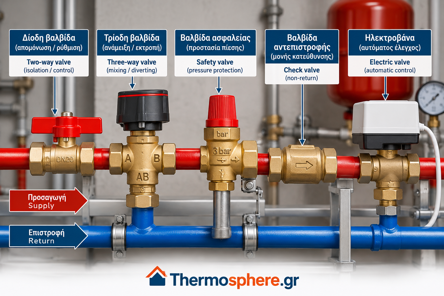
Heating System Valves: Types, Functions, Selection and Common Problems
Valves are essential components of hydronic heating systems. They control water flow, regulate circulation, direct hot water between different circuits and contribute to safe and efficient system operation.
Correct valve selection, installation and maintenance directly affect system performance, reliability and controllability.
This comprehensive guide explains the main types of heating system valves, their operating principles, typical applications, common faults and troubleshooting methods.
1. What Are Heating System Valves?
Heating system valves are mechanical or electromechanical devices designed to control, restrict, stop or redirect water flow within a hydronic heating installation.
Depending on their design, valves can perform several functions:
Isolating individual sections of a heating system.
Regulating water flow rates.
Controlling supply temperatures through mixing.
Preventing reverse circulation.
Protecting equipment against excessive pressure.
Automatically controlling heating zones.
Maintaining or limiting differential pressure.
Different valve types serve different purposes. Installing an unsuitable valve can cause poor temperature control, excessive pressure losses, noise or operational problems.
2. Two-Way Valves
Two-way valves have two connections: one inlet and one outlet.
They are commonly used to isolate a circuit or regulate the amount of water passing through it.
Typical applications
Radiator heating circuits.
Fan coil units operating in heating mode.
Heating manifolds.
Individual heating zones.
Heat pump heating circuits.
How do two-way valves work?
A two-way control valve changes the available flow passage, thereby regulating water flow.
Some valves operate in two positions, fully open or fully closed. Others provide proportional control, allowing intermediate positions.
Important: Standard ball valves intended for isolation should not automatically be used for precise flow regulation. Dedicated control valves provide more suitable flow characteristics.
3. Three-Way Valves
Three-way valves have three ports and are designed for mixing or diverting water flow.
Their operation depends on the internal construction and intended application.
Three-way mixing valves
A mixing valve combines two water streams at different temperatures to produce a controlled outlet temperature.
Typical applications include:
Underfloor heating systems.
Heating installations with multiple temperature requirements.
Mixed radiator and underfloor heating circuits.
Secondary heating circuits requiring lower supply temperatures.
For example, an underfloor heating circuit may require a lower supply temperature than conventional radiators.
A correctly selected three-way mixing valve allows the supply temperature to be adjusted according to the requirements of the circuit.
Three-way diverting valves
Diverting valves direct water toward different outlets.
A common application is switching between space heating and domestic hot water cylinder charging, where supported by the system design.
Important: Not every three-way valve is suitable for both mixing and diverting applications. Always verify the manufacturer’s specifications and port identification.
4. Check Valves
Check valves, also called non-return valves, allow water to flow in one direction while preventing reverse flow.
They are particularly useful in systems with multiple circulation pumps or parallel hydraulic circuits.
Typical applications
Multiple-pump heating systems.
Parallel heating circuits.
Prevention of unwanted reverse circulation.
Prevention of unintended circulation through inactive branches.
Common check valve problems
Debris preventing proper closure.
Mechanical wear.
Incorrect installation direction.
Excessive pressure drop caused by inappropriate sizing.
The correct flow direction is normally indicated by an arrow on the valve body.
Check valves must also be installed according to the manufacturer’s permitted orientation.
5. Safety Valves
Safety valves protect heating systems against excessive pressure by releasing water when a specified opening pressure is reached.
The required pressure rating depends on the equipment, system design and applicable requirements.
In many domestic sealed heating systems, a 3-bar safety valve is commonly used. However, this is not a universal specification for every installation.
Why does a heating safety valve leak?
Possible causes include:
Excessive system filling pressure.
Incorrect expansion vessel pre-charge.
A damaged expansion vessel diaphragm.
Pressure increases during heating.
Debris or wear affecting the valve seat.
A faulty filling mechanism.
Repeated discharge from a safety valve requires investigation of the underlying cause.
Safety warning: Never block, cap or isolate a safety valve discharge connection. Safety valves must be selected, installed and replaced according to the equipment manufacturer’s requirements and applicable safety standards.
6. Motorized and Electrically Operated Valves
Motorized valves use electrical actuators to control water flow automatically.
Depending on the design, the actuator may be electric motor-driven or electrothermal.
Common applications
Automatic heating zone control.
Underfloor heating manifolds.
Thermostat-controlled heating circuits.
Building management systems.
Automated heating installations.
How do they operate?
A thermostat or control system sends an electrical signal to the actuator.
The actuator opens, closes or modulates the valve according to the control strategy.
Common problems
Faulty actuator.
Missing electrical supply.
Incorrect control signal.
Mechanical blockage.
Incorrect actuator voltage.
Thermostat or controller malfunction.
Troubleshooting should distinguish between electrical control faults and mechanical valve problems.
Electrical testing and repairs must be carried out by appropriately qualified personnel.
7. Differential Pressure Control Valves
Differential pressure control valves are used to maintain or limit the pressure difference across selected sections of a hydronic heating system.
In variable-flow installations, differential pressure changes as individual control valves open and close.
Excessive differential pressure can contribute to:
Unwanted valve noise.
Excessive flow through heating circuits.
Unstable temperature control.
Poor control valve performance.
Correctly selected differential pressure controllers can help stabilize hydraulic conditions.
It is important to distinguish differential pressure control valves from differential pressure bypass valves.
A differential pressure controller regulates pressure across a designated circuit, while a bypass valve opens a bypass path when its operating conditions are met.
These devices are not interchangeable in every application.
8. How to Select the Correct Heating Valve
Valve selection should not be based only on pipe diameter.
Several technical parameters must be considered.
Nominal diameter (DN)
The nominal diameter must be compatible with the system’s hydraulic design and connection requirements.
Nominal pressure (PN)
The pressure rating must be suitable for the operating conditions and the relevant temperature range.
Operating temperature
The valve body, seals and internal components must withstand the expected water temperatures.
Flow coefficient (Kv and Kvs)
The flow coefficient describes the relationship between water flow and pressure drop across a valve.
For water under standard reference conditions, the approximate relationship is:
Q = Kv × √Δp
Where:
Q = volumetric flow rate in m³/h.
Kv = flow coefficient.
Δp = pressure drop across the valve in bar.
The Kvs value represents the rated flow coefficient of a fully open valve under specified reference conditions.
Example calculation
Suppose a valve has:
Kv = 2.5
Δp = 0.16 bar
The estimated flow rate is:
Q = 2.5 × √0.16
Q = 2.5 × 0.4
Q = 1.0 m³/h
This simplified calculation is useful for preliminary hydraulic evaluation.
Actual valve selection must also consider control characteristics, valve authority, minimum and maximum operating pressures, fluid properties and manufacturer data.
9. Common Heating Valve Problems and Troubleshooting
Problem 1: A radiator does not heat properly
Possible causes:
Closed or stuck valve.
Insufficient water flow.
Air trapped in the heating circuit.
Circulation pump problems.
Incorrect hydraulic balancing.
A cold radiator does not necessarily indicate a defective valve.
Problem 2: Whistling or unusual valve noise
Possible causes:
Excessive differential pressure.
High water velocity.
Incorrect valve sizing.
Unfavorable operating conditions.
The solution may require hydraulic adjustment rather than valve replacement.
Problem 3: Three-way valve fails to regulate temperature
Possible causes:
Incorrect port connections.
Faulty actuator.
Incorrect sensor readings.
Controller malfunction.
Mechanical blockage.
Insufficient temperature difference between incoming flows.
Diagnosis should include checking the actual water temperatures and the valve control signal.
Problem 4: Water leaks from a valve
Possible leakage points include:
Threaded connections.
Valve stem seals.
Valve body.
Internal sealing components.
Before mechanical intervention, the relevant circuit must be isolated, depressurized and allowed to cool to a safe temperature.
10. Maintenance and Preventive Measures
Regular inspection helps maintain reliable valve operation.
Recommended practices include:
Checking for visible leaks.
Monitoring heating system pressure.
Maintaining appropriate system water quality.
Cleaning installed strainers where necessary.
Checking actuator operation.
Inspecting safety devices according to manufacturer instructions.
Verifying hydraulic settings after major system modifications.
Maintenance intervals depend on the installation, equipment specifications and operating conditions.
Safety-critical components should be inspected by qualified technicians.
11. Frequently Asked Questions
What is the difference between a two-way and a three-way valve?
A two-way valve controls flow between two connections. A three-way valve mixes or diverts water between three ports, depending on its design.
Can a faulty three-way valve affect heating performance?
Yes. A malfunctioning three-way valve can cause incorrect supply temperatures or unwanted flow distribution.
Why do heating valves make noise?
Common causes include excessive differential pressure, high flow velocity, inappropriate valve sizing and incorrect hydraulic settings.
Should all heating valves be replaced periodically?
Not necessarily. Replacement depends on valve condition, performance, maintenance requirements and manufacturer recommendations.
Can incorrect valve selection increase energy consumption?
Yes. Poor valve sizing and unsuitable control strategies can contribute to inefficient circulation, unstable temperature control and unnecessary pumping energy consumption.
Conclusion
Heating system valves are essential for safe, reliable and efficient hydronic heating operation.
Each valve type serves a specific purpose, from flow isolation and temperature regulation to pressure protection and automatic zone control.
Correct valve selection requires an understanding of hydraulic flow, pressure losses, operating temperatures and system control requirements.
Proper coordination between valves, circulation pumps, control systems and hydraulic balancing is essential for achieving stable heating performance.
For reliable operation, installation and troubleshooting should always follow the manufacturer’s technical instructions and the requirements of the specific heating system.
Technical References
CIBSE — Commissioning Code W: Water Distribution Systems.
CIBSE — Guide B1: Heating.
EN 215 — Thermostatic Radiator Valves: Requirements and Test Methods.
EN 1489 — Building Valves: Pressure Safety Valves.
Danfoss — Technical documentation for hydronic balancing and control valves.
IMI Hydronic Engineering — Technical documentation for hydronic balancing and differential pressure control.
ESBE — Technical documentation for mixing and diverting valves.
This article is intended for technical education and general information. It does not replace installation-specific engineering design, manufacturer instructions or professional safety assessments.