
Balancing Valves: Static, Dynamic and PICV – Operation, Selection and Adjustment
Balancing valves are essential components of hydronic heating installations. Their primary purpose is to help distribute water correctly between different heating circuits, ensuring that each radiator, branch or heating zone receives the required flow rate.
In an improperly balanced installation, some circuits may receive excessive water flow while others operate below their design requirements.
To address these problems, engineers use static balancing valves, automatic dynamic balancing valves and pressure-independent control valves (PICVs).
Although these devices serve related purposes, their operating principles, capabilities and applications differ significantly.
This guide explains how each valve type works, how to select the appropriate solution and how to identify common installation and operating problems.
1. What Is a Balancing Valve?
A balancing valve is a hydraulic component designed to regulate or limit water flow through a heating circuit.
Its purpose is to help achieve the flow rates specified by the hydraulic design.
Correct balancing can contribute to:
More consistent heating performance.
Reduced excessive flow through individual circuits.
Improved control valve operation.
Lower risk of hydraulic noise.
More stable system operation.
Reduced unnecessary energy consumption where appropriate conditions exist.
However, balancing valves cannot compensate for fundamentally incorrect pipe sizing, insufficient pump capacity or unsuitable heating emitter selection.
2. Static Balancing Valves
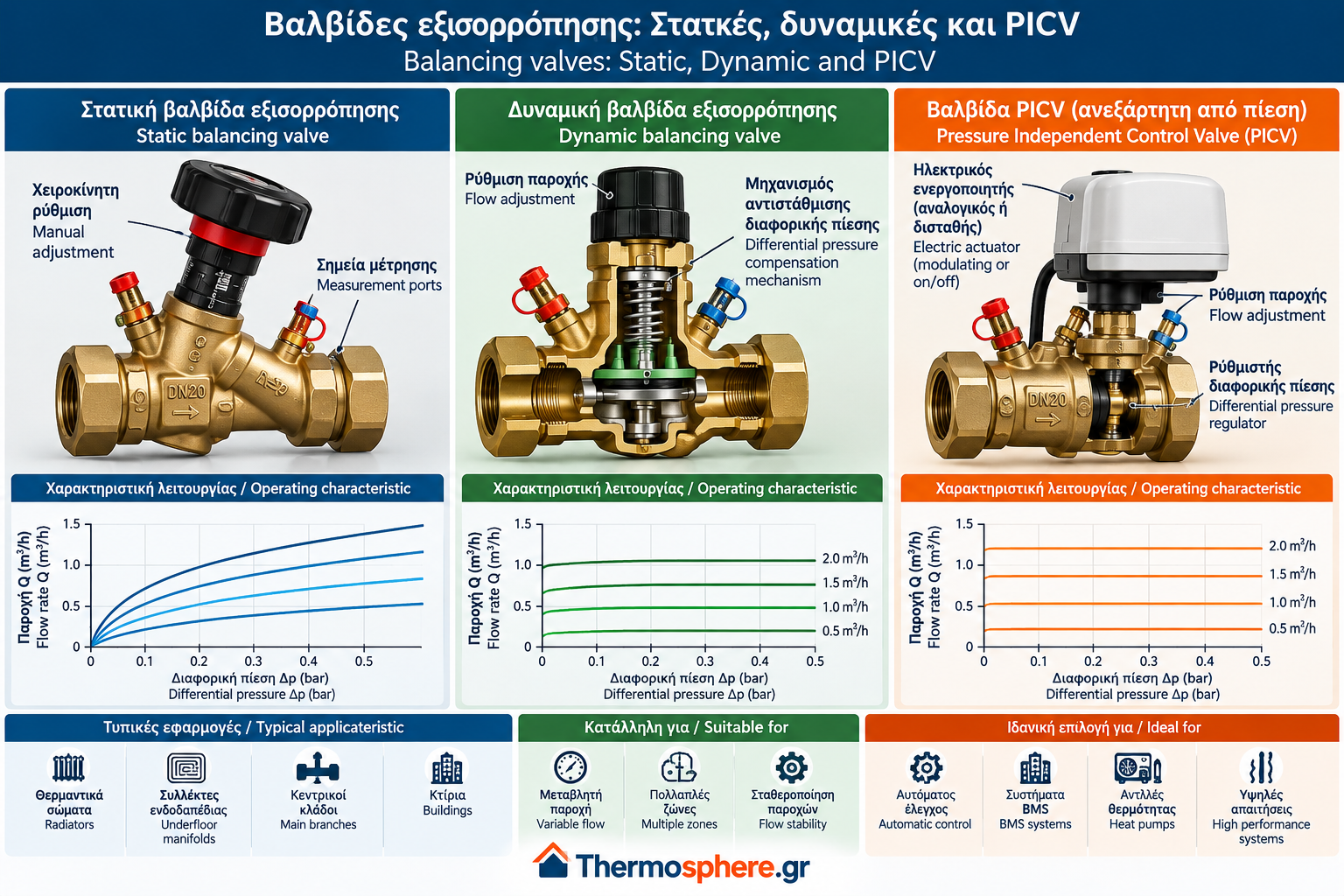
Static balancing valves, also known as manual balancing valves, create an adjustable hydraulic resistance within a circuit.
The technician sets the valve opening to achieve the required flow rate under the intended operating conditions.
How do static balancing valves work?
The valve incorporates a manually adjustable mechanism that changes the available flow passage.
Many models include differential pressure measurement ports.
Using a suitable measuring instrument and the manufacturer’s valve characteristics, technicians can determine the flow rate and adjust the valve accordingly.
Advantages
Relatively simple construction.
Accurate initial adjustment when correctly measured.
Suitable for various hydronic circuits.
No electrical supply required.
Flow measurement capability on suitable models.
Limitations
Static balancing valves do not automatically maintain constant flow when differential pressure changes.
If other control valves close, the available differential pressure may increase and alter flow through the manually balanced circuit.
Typical applications
Relatively constant-flow heating systems.
Main heating branches.
Heating manifolds.
Installations designed for manual hydraulic balancing.
3. Dynamic Balancing Valves
Dynamic balancing valves incorporate a mechanism that compensates for differential pressure variations.
Depending on their design, they maintain or limit water flow within a specified operating range.
How do dynamic balancing valves work?
When the available differential pressure changes, the internal regulating mechanism adjusts hydraulic resistance.
This helps maintain the selected flow rate, provided the valve operates within its specified differential pressure range.
Advantages
Reduced risk of excessive flow.
Automatic compensation for pressure variations.
Less need for repeated manual balancing.
Suitable for many variable-flow installations.
Limitations
A minimum differential pressure is required.
Maximum operating pressure limits must be respected.
Incorrect sizing may cause insufficient flow.
Proper hydraulic compatibility must be verified.
Typical applications
Dynamic balancing valves are used in heating networks with varying hydraulic conditions, including installations with multiple heating zones and automatically operated control valves.
4. Pressure-Independent Control Valves (PICVs)
PICV stands for Pressure Independent Control Valve.
A PICV combines a control valve with a differential pressure regulating mechanism.
It allows the water flow to be controlled while compensating for changes in the available differential pressure within its specified operating range.
How does a PICV work?
A typical PICV includes:
A flow control mechanism.
An internal differential pressure regulator.
A maximum flow presetting function.
Compatibility with a suitable actuator, depending on the model.
The actuator adjusts the control valve opening according to the heating control system’s command.
The differential pressure regulator compensates for pressure variations, helping maintain predictable control characteristics.
Advantages
Combines balancing and flow control.
Limits maximum flow.
Provides more stable control characteristics.
Suitable for automated heating systems.
Can operate with modulating actuators.
Limitations
Often higher initial cost than basic manual valves.
Requires adequate minimum differential pressure.
Correct actuator selection is essential.
Internal mechanisms may be sensitive to contamination.
Typical applications
PICVs are commonly used in automatically controlled heating circuits, terminal units, heating zones and other suitable hydronic applications.
5. Static vs Dynamic vs PICV: Key Differences
Feature | Static | Dynamic | PICV |
Manual flow presetting | Yes | Usually | Usually |
Differential pressure compensation | No | Yes | Yes |
Automatic flow control from BMS | Not as a standalone balancing valve | Not as a standalone flow limiter | Yes, with a suitable actuator |
Suitable for variable-flow systems | Under certain conditions | Yes, depending on application | Yes |
Minimum regulating differential pressure | No separate compensation mechanism threshold | Required | Required |
Primary function | Manual balancing | Automatic flow limitation | Balancing and active flow control |
Actual capabilities depend on the valve model and manufacturer.
6. Flow Calculation and the Kv Coefficient
Correct valve selection requires knowledge of the design flow rate.
For water under standard reference conditions, the following approximate relationship is commonly used:
Q = Kv × √Δp
Where:
Q = volumetric flow rate in m³/h.
Kv = valve flow coefficient.
Δp = pressure drop across the valve in bar.
Example calculation
Consider a valve with:
Kv = 1.5
Δp = 0.16 bar
The calculated flow rate is:
Q = 1.5 × √0.16
Q = 1.5 × 0.4
Q = 0.6 m³/h
This corresponds to approximately 600 litres per hour.
This equation describes the relationship between flow and pressure drop for a given valve characteristic.
For dynamic balancing valves and PICVs, the manufacturer’s selection charts and operating pressure ranges must also be considered.
7. How to Select the Correct Balancing Valve
Valve selection should be based on the hydraulic design and operating conditions.
Required flow rate
The design water flow rate for each circuit must be known.
Available differential pressure
Verify that the available pressure is sufficient for both the valve and the remaining circuit components.
System operating characteristics
Constant-flow and variable-flow installations have different balancing requirements.
Temperature and pressure ratings
The valve must be suitable for the expected operating temperature and pressure range.
Water quality
Filtration and water quality requirements must comply with the manufacturer’s specifications.
Control system compatibility
For PICVs, check actuator compatibility, including:
Supply voltage.
Control signal.
Required actuator stroke.
Mechanical connection.
Control strategy.
8. Installation and Commissioning
Balancing valves must be installed according to the manufacturer’s instructions.
Important installation checks include:
Confirming the correct flow direction.
Verifying connection compatibility.
Providing required straight pipe lengths where specified.
Flushing the system before commissioning.
Checking available differential pressure.
Setting the required flow rate.
Verifying operation under appropriate conditions.
Recording final valve settings.
Presetting should never be based on guesswork.
In complex systems, repeated measurements and adjustments may be necessary.
9. Common Problems and Troubleshooting
Insufficient water flow
Possible causes include:
Incorrect presetting.
Insufficient available differential pressure.
Blocked strainers.
Contamination inside the valve.
Incorrect valve sizing.
Excessive water flow
Possible causes include:
Incorrect static balancing settings.
Unsuitable flow limiting equipment.
Incorrect installation.
Failure of the pressure compensation mechanism.
Valve noise
Noise may result from excessive differential pressure, high water velocity or operation outside the manufacturer’s specified range.
PICV not responding to the control system
Check:
Electrical supply.
Control signal.
Actuator compatibility.
Mechanical actuator connection.
Available differential pressure.
Valve mechanism condition.
Troubleshooting should distinguish electrical control faults from hydraulic problems.
10. Maintenance and Preventive Measures
Maintenance requirements depend on the valve type and manufacturer.
Recommended practices include:
Inspecting for leaks.
Checking strainers and filters.
Monitoring differential pressure.
Verifying actual flow where possible.
Checking actuator operation.
Recording changes to valve settings.
Rechecking system performance after major modifications.
Before mechanical maintenance, the relevant circuit must be safely isolated, depressurized and cooled.
Electrical maintenance should be performed by appropriately qualified personnel.
11. Frequently Asked Questions
What is the difference between static and dynamic balancing valves?
A static balancing valve creates a preset hydraulic resistance. A dynamic balancing valve compensates for differential pressure changes within its specified operating range.
Is a PICV the same as a dynamic balancing valve?
Not exactly. A PICV combines differential pressure compensation with active flow control, normally using a compatible actuator.
Does every heating system require PICVs?
No. The appropriate valve type depends on the system design, control strategy and hydraulic operating conditions.
Can incorrect balancing valves increase energy consumption?
Yes. Incorrect valve selection or adjustment may contribute to excessive flow, unnecessary pressure losses and unstable temperature control.
Can a static balancing valve be replaced with a PICV?
Only after checking the hydraulic design, available differential pressure, required control function and compatibility of the replacement valve.
Conclusion
Static balancing valves, dynamic balancing valves and PICVs address different requirements in hydronic heating systems.
Static valves provide manual balancing, dynamic valves compensate for pressure variations, and PICVs combine balancing with automatic flow control.
Correct selection depends on design flow rates, available differential pressure, operating conditions and control requirements.
Proper installation, adjustment and commissioning are essential for reliable and efficient system performance.
Technical References
CIBSE — Commissioning Code W: Water Distribution Systems.
CIBSE — Guide B1: Heating.
EN 14336 — Heating Systems in Buildings: Installation and Commissioning of Water-Based Heating Systems.
Danfoss — Technical documentation for manual and automatic balancing valves and PICVs.
IMI Hydronic Engineering — Technical documentation for STAD, TA-COMPACT-P and differential pressure controllers.
Siemens — Technical documentation for pressure-independent control valves.
This article provides general technical information and does not replace installation-specific engineering design, manufacturer instructions or professional commissioning procedures.