
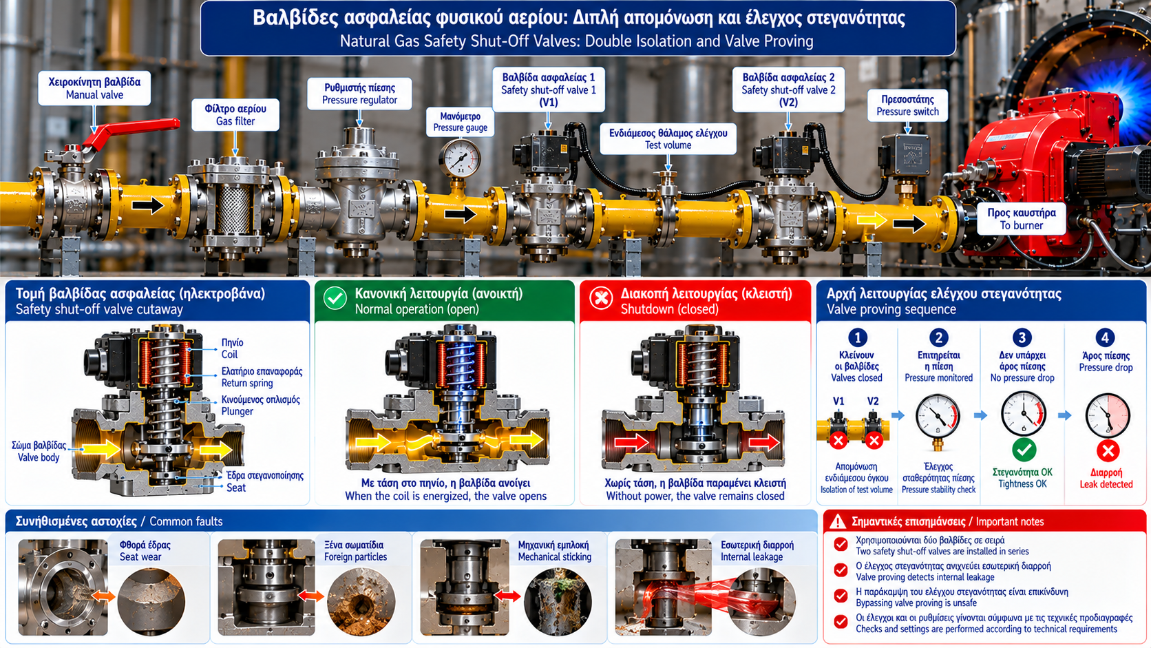
Natural Gas Safety Shut-Off Valves: Double Isolation and Valve Proving
Automatic natural gas safety shut-off valves are critical components of combustion safety systems.
Their primary purpose is to stop fuel flow when a burner shuts down or when the burner management system detects a condition requiring safe shutdown.
Many industrial installations use two automatic shut-off valves in series. Depending on system design, these valves may be combined with a valve proving system (VPS).
1. What Is a Gas Safety Shut-Off Valve?
In burner gas trains, the term safety valve often refers to an automatic safety shut-off valve.
Its function is to interrupt gas flow in accordance with its design specifications and applicable safety requirements.
It should not be confused with a pressure relief valve, which performs a different function.
Safety shut-off valves may use electromagnetic or other suitable actuating mechanisms.
2. Why Are Two Valves Installed in Series?
Many gas trains use two automatic shut-off valves, commonly designated V1 and V2.
The upstream valve provides one isolation barrier, while the downstream valve provides another.
If one valve develops unacceptable internal leakage, the second may still provide isolation if it remains functional.
However, the presence of two valves does not justify operating a burner with a known valve failure.
3. What Is Valve Proving?
Valve proving is a process used to detect unacceptable leakage through automatic gas shut-off valves.
Certain systems monitor pressure changes in a defined volume between two valves.
The proving sequence may occur before startup, after shutdown or during another specified phase.
The actual procedure depends on the proving system and applicable requirements.
4. How Does a Valve Proving System Work?
A typical arrangement may include:
Two automatic safety shut-off valves.
A defined intermediate pipe volume.
Pressure monitoring equipment.
A proving controller or an integrated burner management function.
A specified test sequence.
During the test, the controller evaluates pressure behavior under controlled conditions.
Unexpected pressure changes may indicate unacceptable leakage or another fault.
Test limits and timing must follow the particular device’s specifications.
5. Internal Valve Leakage
Internal leakage occurs when gas passes through a valve that has been commanded closed.
Possible causes include seat deterioration, damaged seals, foreign particles, deformation and mechanical sticking.
Internal leakage may not be externally visible.
It must be distinguished from leakage to the surrounding environment.
6. Internal and External Tightness
Internal tightness refers to the valve’s ability to prevent gas passing through its closed seat.
External tightness refers to the containment of gas within the valve body and its connections.
These characteristics are verified using different procedures.
Successful valve proving does not necessarily replace external tightness testing of the installation.
7. What Happens When Valve Proving Fails?
If the proving system detects an unacceptable condition, the burner controller prevents startup or initiates its specified safe response.
Possible causes include leakage through either valve, pressure monitoring faults, intermediate pipework leakage or incorrect test conditions.
An alarm does not always identify the exact defective component.
Qualified troubleshooting is required.
8. Integration with Burner Management
Safety shut-off valves operate within the burner safety chain.
Their operation is coordinated with ignition sequencing, flame supervision, gas pressure monitoring, combustion air proving and other applicable safety limits.
A critical fault should result in the required safe response.
Removing electrical power alone does not prove that a mechanically defective valve has achieved tight shut-off.
9. Common Failures
Valve Fails to Open
The burner may fail to complete its ignition sequence.
Valve Fails to Close Tightly
Valve proving may detect unacceptable leakage.
Repeated Valve Proving Alarms
Gas pressure conditions, valve integrity and proving equipment require investigation.
Electrical or Mechanical Failure
Actuator faults or internal mechanical problems can prevent correct valve operation.
10. Inspection and Maintenance
Inspections must be performed by appropriately qualified and authorized personnel.
A maintenance program may include visual inspection, electrical checks, verification of the shutdown sequence, valve proving tests and approved internal or external tightness tests.
Findings and corrective actions should be documented.
Valve proving functions must never be bypassed to force burner startup.
11. Technical Standards
Relevant standards include:
EN 161: Automatic shut-off valves for gas burners and gas appliances.
EN 1643: Valve proving systems for automatic shut-off valves.
EN 676: Forced draught burners for gaseous fuels, within the standard’s scope.
Specific requirements depend on the installation and applicable regulatory framework.
Conclusion
Automatic gas safety shut-off valves and valve proving systems are important elements of combustion safety.
Two valves in series provide additional isolation capability, while valve proving systems can detect unacceptable internal leakage within their specified operating limits.
Correct design, periodic verification and prompt investigation of failures are essential for safe burner operation.