
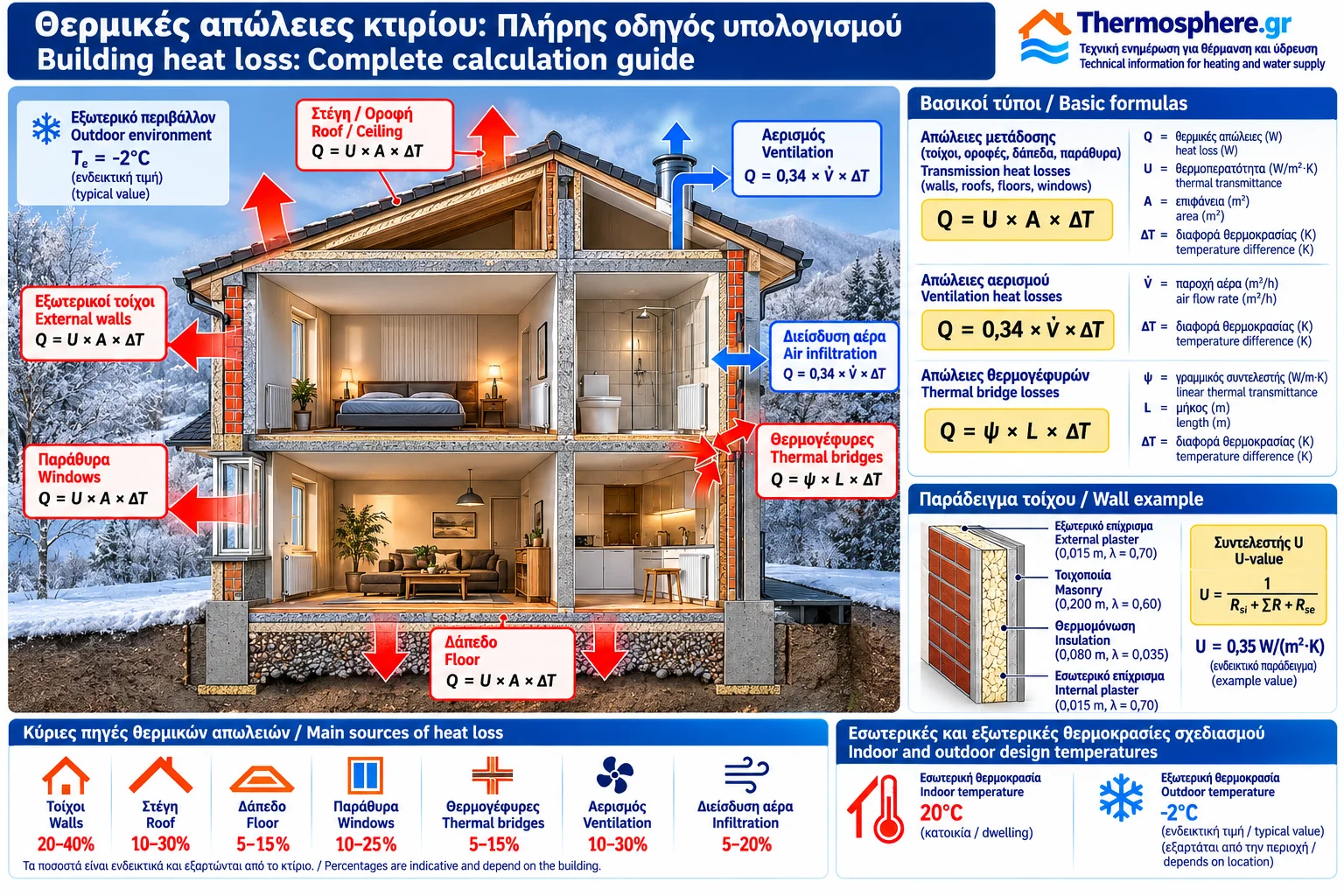
Building Heat Loss: Complete Calculation Guide
Heat loss is one of the most important parameters in the design of a heating system. It determines the heating capacity required to maintain the desired indoor temperature under design conditions.
Every heated building exchanges heat with its surroundings. During winter, when outdoor temperatures are lower than indoor temperatures, heat flows from warmer indoor spaces toward the colder environment.
Heat transfer occurs through the building envelope, thermal bridges, ventilation and unwanted outdoor air infiltration.
Accurate heat loss calculations are essential for sizing boilers, heat pumps and radiators.
1. What Is Building Heat Loss?
Building heat loss is the rate at which thermal energy is transferred from a heated space to a colder environment.
In heating design, it is normally expressed in watts (W) or kilowatts (kW).
For example, a room with a design heat loss of 2,000 W requires approximately 2,000 W of net heating input to maintain its design indoor temperature under the specified steady-state conditions, assuming other heat gains are not included.
Two quantities must be distinguished:
Heat transfer rate (W or kW): The instantaneous rate of heat transfer.
Thermal energy (kWh): The amount of energy transferred over a period of time.
Design heat loss is not the same as annual energy consumption.
2. Where Does a Building Lose Heat?
The main categories are:
Transmission Heat Loss
Heat transferred through building elements, including:
External walls.
Roofs and ceilings.
Floors.
Windows.
External doors.
Elements adjoining unheated spaces.
Thermal Bridge Heat Loss
Additional heat flow through local regions where geometry, materials or insulation discontinuities affect heat transfer.
Ventilation Heat Loss
Heat required to warm incoming outdoor ventilation air.
Air Infiltration Heat Loss
Heat loss associated with uncontrolled outdoor air entering through gaps, joints and other leakage paths.
Ventilation and infiltration must be combined without double-counting the same airflow.
3. How Is Heat Transferred?
Heat transfer occurs through three main mechanisms.
Conduction: Heat transfer through materials such as brick, concrete and insulation.
Convection: Heat transfer between a surface and a moving or stationary fluid, such as air.
Radiation: Heat transfer through electromagnetic radiation.
In building element U-value calculations, surface thermal resistances account for combined convective and radiative effects under specified conditions.
4. Basic Heat Loss Formula
For a planar building element separating two environments, a simplified calculation is:
Φ = U × A × ΔT
Where:
Φ = heat transfer rate in W.
U = thermal transmittance in W/(m²·K).
A = element area in m².
ΔT = temperature difference in K or °C.
This relationship applies under steady-state assumptions using appropriate boundary temperatures and U-values.
Special cases, including ground-contact floors, require additional or alternative calculation methods.
5. External Wall Heat Loss Example
Assume an external wall with:
Area: 20 m².
U-value: 0.50 W/(m²·K).
Indoor temperature: 20°C.
Outdoor temperature: 0°C.
Temperature difference:
ΔT = 20 K
Heat loss:
Φ = 0.50 × 20 × 20
Φ = 200 W
If outdoor temperature decreases to −5°C, the temperature difference becomes 25 K and heat loss increases to 250 W.
This illustrates the importance of outdoor design temperature selection.
6. What Is the U-Value?
The U-value describes the heat transfer rate through a building element per unit area and unit temperature difference.
Its unit is:
W/(m²·K)
A lower U-value indicates less heat transfer under the same conditions.
For comparison:
U-Value | Interpretation |
|---|---|
2.00 W/(m²·K) | High thermal transmittance |
1.00 W/(m²·K) | Lower transmittance |
0.50 W/(m²·K) | Significantly reduced transmittance |
0.25 W/(m²·K) | Low thermal transmittance |
These values are illustrative comparisons, not universal regulatory limits.
7. What Is Thermal Conductivity λ?
Thermal conductivity λ is a material property describing its ability to conduct heat.
Its unit is:
W/(m·K)
A lower λ means greater resistance to conductive heat transfer for the same material thickness.
Different insulation products may have declared conductivity values around 0.030–0.045 W/(m·K).
Actual calculations must use appropriate product-specific declared or design values.
8. What Is Thermal Resistance R?
For a homogeneous material layer:
R = d / λ
Where:
R = thermal resistance in m²·K/W.
d = thickness in m.
λ = thermal conductivity in W/(m·K).
Example:
Insulation thickness = 0.08 m
Thermal conductivity = 0.035 W/(m·K)
R = 0.08 / 0.035
R ≈ 2.29 m²·K/W
This is the resistance of the insulation layer only.
Other layers and surface resistances must be included for the complete element.
9. Calculating the U-Value of a Multilayer Wall
For a simple planar element with homogeneous layers:
U = 1 / (Rsi + ΣR + Rse)
Where:
Rsi = internal surface resistance.
ΣR = sum of material layer resistances.
Rse = external surface resistance.
Consider the following illustrative wall:
Layer | Thickness | λ | R |
|---|---|---|---|
Internal plaster | 0.015 m | 0.70 | 0.021 |
Masonry | 0.20 m | 0.60 | 0.333 |
Insulation | 0.08 m | 0.035 | 2.286 |
External plaster | 0.015 m | 0.70 | 0.021 |
Thermal resistance values are in m²·K/W and conductivity values in W/(m·K).
For an illustrative external wall with horizontal heat flow:
Rsi = 0.13 m²·K/W
Rse = 0.04 m²·K/W
Total resistance:
Rtotal = 0.13 + 0.021 + 0.333 + 2.286 + 0.021 + 0.04
Rtotal ≈ 2.83 m²·K/W
Therefore:
U = 1 / 2.83
U ≈ 0.353 W/(m²·K)
This simplified example assumes homogeneous layers.
Actual constructions with cavities, structural elements or other non-uniformities require appropriate calculation methods.
10. How Does Insulation Reduce Heat Loss?
Insulation increases thermal resistance and reduces U-value.
For the same wall without the insulation layer:
Rtotal ≈ 0.545 m²·K/W
U ≈ 1.83 W/(m²·K)
With insulation:
U ≈ 0.353 W/(m²·K)
For a 20 m² wall and a 20 K temperature difference:
Without insulation:
Φ ≈ 1.83 × 20 × 20 = 732 W
With insulation:
Φ ≈ 0.353 × 20 × 20 = 141 W
The transmission heat loss through this particular wall decreases by approximately 81%.
This does not imply an 81% reduction in total building heat loss or annual energy consumption.
11. Heat Loss Through Windows
Windows are an important part of the building heat balance.
Overall window thermal transmittance is commonly designated Uw.
It should not be confused with:
Ug: glazing thermal transmittance.
Uf: frame thermal transmittance.
Uw depends on glazing, frame properties, geometry and thermal effects around glazing edges.
Example:
Window area = 4 m²
Uw = 1.50 W/(m²·K)
ΔT = 20 K
Φ = 1.50 × 4 × 20
Φ = 120 W
This calculation concerns transmission heat loss and excludes air leakage through window joints.
12. Heat Loss Through Roofs and Ceilings
Ceilings and roofs can lose heat toward outdoor air or unheated spaces.
Calculation depends on the construction arrangement:
Ceiling directly exposed to outdoor conditions.
Ceiling below an unheated attic.
Insulated roof assembly.
Flat roof with multiple material layers.
The applicable temperature difference varies with the boundary conditions.
Surface thermal resistances also depend on heat flow direction.
13. Heat Loss Through Floors
Floors may adjoin:
Outdoor air.
Unheated basements.
Other indoor spaces.
The ground.
Floors exposed to outdoor air can be assessed using appropriate thermal transmittance methods.
Ground-contact floors require more specialised calculations.
Heat transfer depends on building geometry, perimeter, floor insulation, ground properties and other factors.
Relevant methods are provided in standards such as EN ISO 13370.
Applying the outdoor air temperature directly across the entire ground-contact floor can produce inaccurate results.
14. What Are Thermal Bridges?
A thermal bridge is a region of the building envelope where heat flow differs from adjacent areas due to geometry, materials or insulation discontinuities.
Common locations include:
Wall-to-floor junctions.
Beams and columns.
Window perimeters.
Balconies.
Building corners.
Roof-to-wall junctions.
Thermal bridges may increase heat loss and reduce internal surface temperatures.
Under certain conditions, they can increase the risk of surface condensation and mould growth.
15. Calculating Thermal Bridge Heat Loss
For a linear thermal bridge:
Φtb = ψ × L × ΔT
Where:
ψ = linear thermal transmittance in W/(m·K).
L = thermal bridge length in m.
ΔT = temperature difference in K.
Example:
ψ = 0.15 W/(m·K)
L = 12 m
ΔT = 20 K
Φtb = 0.15 × 12 × 20
Φtb = 36 W
The ψ-value must correspond to the actual construction detail and the dimensional reference convention used.
Surface transmission and thermal bridge calculations must use consistent geometry to prevent double-counting.
16. What Is Ventilation Heat Loss?
Ventilation replaces indoor air with outdoor air.
When outdoor air is colder, heating energy is required to bring it to the desired indoor temperature.
A simplified sensible heating load relationship is:
Φv ≈ 0.34 × V̇ × ΔT
Where:
Φv = ventilation heat load in W.
V̇ = outdoor airflow in m³/h.
ΔT = temperature difference in K.
The factor 0.34 is based on approximate air density and specific heat capacity.
The formula does not automatically account for heat recovery.
17. Ventilation Heat Loss Example
Assume:
Room volume = 100 m³
Air change rate = 0.5 h⁻¹
Temperature difference = 20 K
Airflow:
V̇ = 100 × 0.5
V̇ = 50 m³/h
Ventilation heat load:
Φv ≈ 0.34 × 50 × 20
Φv ≈ 340 W
This is an illustrative calculation.
Actual ventilation requirements depend on room use and applicable requirements.
18. What Is Air Infiltration?
Air infiltration is uncontrolled outdoor air entering through imperfections in the building envelope.
It is influenced by:
Airtightness.
Wind.
Indoor-outdoor temperature differences.
Building height.
Mechanical ventilation pressures.
Window and door operation.
Infiltration cannot be reliably determined from building age alone.
Airtightness measurements and appropriate modelling methods may be used.
19. What Does n50 Mean?
The n50 value represents the air change rate measured or derived during an airtightness test at a 50 Pa pressure difference.
It is an important indicator of building airtightness.
However, n50 is not the normal natural air change rate during everyday building operation.
Converting n50 into an infiltration estimate requires an appropriate method and additional assumptions.
It should not be inserted directly into a normal ventilation heat loss calculation as if it represented actual operating air changes.
20. Indoor and Outdoor Design Temperatures
Heat loss calculations require defined indoor and outdoor design temperatures.
Indoor design temperature depends on room use.
Outdoor design temperature depends on location and applicable climatic design data.
It is not necessarily the lowest temperature ever recorded.
For example:
Indoor temperature = 20°C
Outdoor temperature = −2°C
ΔT = 22 K
Regulatory design calculations use the applicable temperature data and corrections required by the selected method.
21. Complete Simplified Room Heat Loss Example
Consider a hypothetical room with an indoor temperature of 20°C and an outdoor temperature of 0°C.
For simplicity, all listed elements are assumed to be exposed directly to outdoor air, and their U-values are already known.
Building Element | Area | U-Value | Heat Loss |
|---|---|---|---|
External walls, net area | 18 m² | 0.50 | 180 W |
Windows | 4 m² | 1.50 | 120 W |
Roof exposed to outdoor air | 20 m² | 0.35 | 140 W |
Floor exposed to outdoor air | 20 m² | 0.45 | 180 W |
Total transmission heat loss:
ΦT = 620 W
Assume additional thermal bridge heat loss:
Φtb = 50 W
Room volume:
50 m³
Assume a total effective outdoor air change rate of 0.5 h⁻¹ for this example, without separately counting the same airflow as both ventilation and infiltration.
Airflow:
V̇ = 50 × 0.5 = 25 m³/h
Air exchange heat loss:
Φv ≈ 0.34 × 25 × 20
Φv ≈ 170 W
Total:
Φtotal = 620 + 50 + 170
Φtotal = 840 W
The simplified room heat loss is approximately:
0.84 kW
This example is not a complete EN 12831 design calculation.
It excludes additional corrections, special boundary conditions and potential additional heating requirements.
22. Heat Loss vs Design Heating Load
Transmission and ventilation heat losses are the main components of design heating load.
However, a complete calculation may include additional requirements or adjustments depending on the method and building use.
For example, some applications consider additional capacity for reheating rooms after temperature setback periods.
Such additional capacity should not be applied as an arbitrary percentage in every installation.
23. Heat Loss vs Annual Energy Consumption
Heat loss changes as outdoor conditions change.
A building requiring 8 kW at design conditions does not continuously consume 8 kWh every hour throughout winter.
Annual heating demand depends on:
Climate.
Heating season duration.
Indoor temperature settings.
Internal heat gains.
Solar gains.
Ventilation.
Thermal mass.
Occupancy and operating schedules.
Fuel or electricity consumption also depends on heating system efficiency.
24. How Can Building Heat Loss Be Reduced?
Building Envelope Insulation
Improve wall, roof and appropriate floor insulation.
Better Windows
Select suitable glazing, frames and installation details.
Thermal Bridge Reduction
Maintain insulation continuity and improve junction details.
Airtightness Improvements
Reduce unwanted air leakage while maintaining necessary ventilation.
Heat Recovery Ventilation
Where appropriate, heat recovery can reduce the heating requirement associated with outdoor ventilation air.
The best measures depend on the specific building.
25. Common Heat Loss Calculation Mistakes
Using Floor Area Alone
Building area does not fully describe design heating load.
Applying Generic W/m² Rules
These may support very early estimates but cannot replace detailed calculations.
Ignoring Thermal Bridges
This can underestimate heat loss.
Ignoring Ventilation
This can significantly underestimate heating requirements.
Double-Counting Ventilation and Infiltration
This can overestimate the heating load.
Incorrect Ground Floor Calculations
Using outdoor air temperature directly for ground-contact floors may be inappropriate.
Using Unsupported U-Values
Actual construction layers and material properties should be established.
Adding Arbitrary Safety Margins
This can lead to oversized heating equipment.
26. Relevant Technical Standards
Important European and international standards include:
EN 12831-1: Method for calculating design heat load for space heating.
EN ISO 6946: Thermal resistance and thermal transmittance of building components.
EN ISO 10077: Thermal performance of windows, doors and shutters.
EN ISO 10211: Detailed thermal bridge calculations.
EN ISO 14683: Simplified methods and values for linear thermal bridges.
EN ISO 13370: Heat transfer through the ground.
EN ISO 9972: Building airtightness testing.
For projects in Greece, applicable KENAK requirements, relevant TOTEE technical guidance and national implementations of standards must also be considered.
The current editions and national requirements should be verified when preparing an actual engineering study.
Conclusion
Building heat loss depends on geometry, materials, insulation, thermal bridges, ventilation and design temperatures.
The basic equation Φ = U × A × ΔT provides a useful calculation method for simple transmission heat loss cases, but it is not sufficient for a complete heating design study.
Accurate design heat load calculations form the basis for selecting appropriately sized boilers, heat pumps and radiators.
Calculate the building's actual heating requirements first, then select the heating system capacity — not the other way around.
This article is intended for technical information. Actual equipment sizing requires an engineering study using appropriate climatic data, standards and building characteristics.
Thermosphere.gr — Technical information for heating and water supply.