
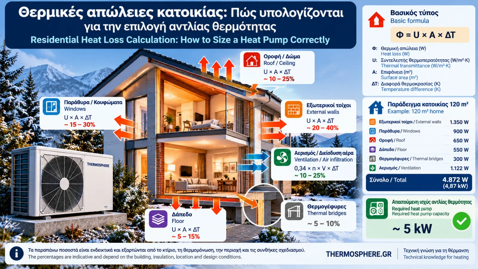
Residential Heat Loss Calculation: How to Size a Heat Pump Correctly
Correct heat pump sizing begins with calculating a building's design heat loss. This is the heating capacity required to maintain the desired indoor temperature under specified cold outdoor conditions.
One of the most common mistakes is selecting a heat pump solely on the basis of floor area.
Two homes measuring 120 m² can have very different heating requirements depending on insulation, windows, location, ventilation and the surfaces exposed to outdoor conditions.
This Thermosphere.gr guide explains the fundamentals of residential heat-loss calculations, provides worked examples and shows how the results inform heat pump selection.
Important: The simplified calculations below are educational examples. They do not replace a complete design heat-load calculation under EN 12831-1 and applicable national parameters.
1. What Is Residential Heat Loss?
Heat loss is the transfer of heat from a heated building to colder surroundings.
Heat escapes primarily through:
External walls.
Windows and doors.
Roofs and ceilings.
Floors.
Thermal bridges.
Ventilation and uncontrolled air infiltration.
The greater the heat loss, the greater the heating capacity needed under design conditions.
Required heating capacity is generally expressed in kilowatts (kW).
2. Heating Capacity vs Energy Consumption
Heating capacity and energy consumption are different quantities.
Heating capacity (kW) is the rate at which heat must be supplied under specific conditions.
Heating energy (kWh) is the total amount of heat supplied over a period.
For example, a building may have a design heating load of 7 kW. This does not mean it requires 7 kW continuously throughout the winter.
Heat loss generally decreases as outdoor temperatures rise.
Design heating load is therefore used for equipment sizing, while annual energy consumption requires a separate calculation.
3. Why Floor Area Alone Is Not Enough
A common rough approach multiplies floor area by an assumed number of watts per square metre.
For example:
120 m² × 70 W/m² = 8,400 W, or 8.4 kW.
This may be useful as a preliminary approximation, but it is not a reliable design calculation.
Actual heat loss depends on:
Insulation quality.
Exposed building-envelope area.
Window-to-wall ratio.
Thermal bridges.
Airtightness.
Ventilation.
Local design outdoor temperature.
Required indoor temperature.
A well-insulated home and an older uninsulated property of identical size should not be assumed to have the same heating load.
4. Basic Heat Transmission Formula
For a simple building element separating two environments at different temperatures, heat loss can be approximated by:
Φ = U × A × ΔT
Where:
Φ: Heat loss in watts (W).
U: Thermal transmittance in W/(m²·K).
A: Surface area in m².
ΔT: Temperature difference in K or °C.
This formula describes the basic physics of heat transmission through the building envelope.
A complete design calculation requires additional treatment of ground contact, unheated adjacent spaces, thermal bridges and other conditions.
5. Worked Example: External Wall
Consider an external wall with:
Area: 25 m².
U-value: 0.50 W/(m²·K).
Indoor temperature: 20°C.
Design outdoor temperature: −2°C.
The temperature difference is:
20 − (−2) = 22 K.
Therefore:
Φ = 0.50 × 25 × 22
Φ = 275 W.
This wall loses approximately 275 W under the assumed design conditions, excluding additional thermal-bridge effects.
6. How Insulation Affects Heat Loss
The U-value describes how much heat passes through one square metre of a building element for each degree of temperature difference.
Lower U-values generally indicate better insulation performance.
Consider two walls of equal area, 25 m², exposed to a 22 K temperature difference.
Parameter | Wall A | Wall B |
|---|---|---|
Area | 25 m² | 25 m² |
U-value | 1.50 W/(m²·K) | 0.35 W/(m²·K) |
Temperature difference | 22 K | 22 K |
Heat loss | 825 W | 192.5 W |
In this example, the better-insulated wall has approximately 77% lower heat loss.
This illustrates why building-envelope quality is essential to heat pump sizing.
7. Heat Loss Through Windows
Windows can contribute significantly to heat loss, particularly where glazing is old or airtightness is poor.
A simplified calculation uses the overall window thermal transmittance, Uw.
Example:
Total window area: 15 m².
Uw: 1.60 W/(m²·K).
Temperature difference: 22 K.
Φ = 1.60 × 15 × 22
Φ = 528 W.
Replacing windows may reduce heat loss, but the actual benefit depends on the properties of both the existing and replacement units.
8. Roof and Floor Heat Loss
Roofs, ceilings and floors must also be included in the assessment.
For a roof directly exposed to outdoor air, the basic U × A × ΔT relationship can provide a simple estimate.
However, floors adjacent to the ground and elements bordering unheated spaces require more specific treatment.
For example, ground-floor heat loss cannot be calculated accurately by simply applying outdoor air temperature to the entire floor surface.
Appropriate standards and correction methods must be used.
9. What Are Thermal Bridges?
A thermal bridge is an area of the building envelope where heat flow differs from surrounding areas because of geometry, materials or construction details.
Common examples include:
Wall-to-floor junctions.
Window perimeter details.
Balconies.
Structural columns and beams.
Connections between different building elements.
Thermal bridges can increase total heat loss and create locally colder internal surfaces.
A complete calculation accounts for them using appropriate linear or point thermal transmittance values.
10. Ventilation and Air Infiltration Heat Loss
Heat is also required to warm outdoor air entering the building.
For a simplified estimate:
Φv ≈ 0.34 × n × V × ΔT
Where:
Φv: Ventilation heat loss in W.
n: Air change rate in h⁻¹.
V: Heated volume in m³.
ΔT: Temperature difference in K.
0.34: Approximate volumetric heat-capacity coefficient for air in Wh/(m³·K).
Example:
Heated volume: 300 m³.
Assumed air change rate: 0.5 h⁻¹.
Temperature difference: 22 K.
Φv ≈ 0.34 × 0.5 × 300 × 22
Φv ≈ 1,122 W.
The air change rate of 0.5 h⁻¹ is an illustrative assumption, not a universal value.
A real assessment must consider ventilation requirements, airtightness, mechanical ventilation and the applicable calculation standard, without double-counting airflow.
11. Calculating Total Heat Loss
Total design heat loss combines transmission and ventilation losses, together with any additional requirements specified by the chosen methodology.
For a simplified educational estimate:
Total heating load ≈ Transmission heat loss + Ventilation heat loss
A complete assessment is performed room by room and then combined to establish the building's total design heating load.
12. Complete Illustrative Example: A 120 m² Home
Consider a hypothetical home with:
Heated floor area: 120 m².
Average ceiling height: 2.5 m.
Heated volume: 300 m³.
Indoor temperature: 20°C.
Assumed design outdoor temperature: −2°C.
Temperature difference: 22 K.
Assume the following component heat losses:
Component | Assumed heat loss |
|---|---|
External walls | 1,350 W |
Windows and external doors | 900 W |
Roof | 650 W |
Floor and adjacent spaces | 550 W |
Thermal bridges | 300 W |
Ventilation and infiltration | 1,122 W |
Total | 4,872 W |
Therefore:
Total illustrative design heating load ≈ 4.87 kW.
This demonstrates why a 120 m² home can have a heating load very different from a rough W/m² estimate.
The individual values are assumed for illustration and are not measurements or calculated results for a specific building.
13. Selecting Heat Pump Capacity
Once the design heating load is established, the available heating capacity of candidate heat pumps must be checked at the appropriate operating conditions.
The manufacturer's nominal capacity alone is insufficient.
Important factors include:
Design outdoor temperature.
Required heating-water flow temperature.
Available capacity under those conditions.
Defrost behaviour.
Minimum modulation capacity.
Backup heating strategy, if applicable.
For example, a home with a calculated load of 4.87 kW does not automatically require any unit marketed as a “5 kW heat pump”.
The actual output of the selected model at design conditions must be verified.
14. Should You Add an Arbitrary Safety Margin?
Adding a large arbitrary percentage to the calculated heating load is not generally sound design practice.
Excessive capacity can cause:
Frequent starts and stops.
Poor operation at low loads.
Higher initial costs.
Suboptimal system performance.
Insufficient capacity can result in inadequate heating during cold design conditions.
Final sizing should follow the heat-load calculation, manufacturer requirements and the selected system operating strategy.
15. Why Location Matters
Design outdoor temperatures vary with geographical location, elevation and local climate.
A coastal home in a mild climate may have a different design load from an otherwise identical home in a mountainous area.
Design temperatures should come from appropriate climate data and applicable national parameters, rather than applying one value to an entire country.
16. Heat Loss and Building Renovation
If insulation or window upgrades are planned, heat pump sizing should account for the building's intended final condition.
Otherwise, a unit selected for the original building may become oversized after renovation.
A sensible process is:
Assess the existing building.
Identify planned energy-efficiency improvements.
Calculate design heat loss for the final building condition.
Check radiator or emitter capacity.
Select and size the heat pump.
17. Common Heat-Loss Calculation Mistakes
Mistake 1: Sizing from floor area alone.
Floor area does not fully describe building heat loss.
Mistake 2: Using an incorrect outdoor design temperature.
Local climate directly affects the heating load.
Mistake 3: Ignoring ventilation and infiltration.
These losses can be significant.
Mistake 4: Omitting thermal bridges.
Transmission losses may be underestimated.
Mistake 5: Using nominal heat pump capacity without checking operating conditions.
Available heat pump output changes with operating conditions.
Mistake 6: Applying excessive safety factors.
Oversizing does not automatically improve reliability or economy.
18. Frequently Asked Questions
How Many kW Does a 100 m² Home Need?
There is no single reliable answer based on floor area alone. Building heat loss, local climate and construction characteristics must be considered.
Can I Calculate Heat Loss Myself?
You can make a preliminary educational estimate. Final equipment selection should be based on a proper design assessment by a qualified professional.
Does External Insulation Reduce Heat Loss?
Yes, when it reduces the thermal transmittance of the relevant building elements and construction details are properly addressed.
Should Heat Loss Be Calculated Room by Room?
Yes. Room-by-room calculations are important both for total equipment sizing and for selecting suitable heat emitters.
Is an Energy Performance Certificate Enough to Size a Heat Pump?
Not by itself. An EPC provides valuable building-energy information, but it does not replace a detailed design heating-load calculation.
Conclusion
Residential heat-loss calculation is the foundation of correct heat pump sizing.
Insulation, windows, ventilation, thermal bridges and design outdoor temperature all influence the result.
Reliable heat pump sizing requires a complete technical assessment, not simply a calculation based on floor area.
Technical References and Further Reading
EN 12831-1 — Energy performance of buildings: Method for calculation of the design heat load.
EN ISO 6946 — Building components and building elements: Thermal resistance and thermal transmittance.
EN ISO 10077-1 — Thermal performance of windows, doors and shutters.
EN ISO 10211 — Thermal bridges in building construction.
EN ISO 13370 — Heat transfer via the ground.
EN 14825 — Seasonal performance of heat pumps.
Greek Technical Directive ΤΟΤΕΕ 20701-1 — National technical parameters for building energy performance assessment.
Thermosphere.gr — Technical knowledge for heating and building systems.