
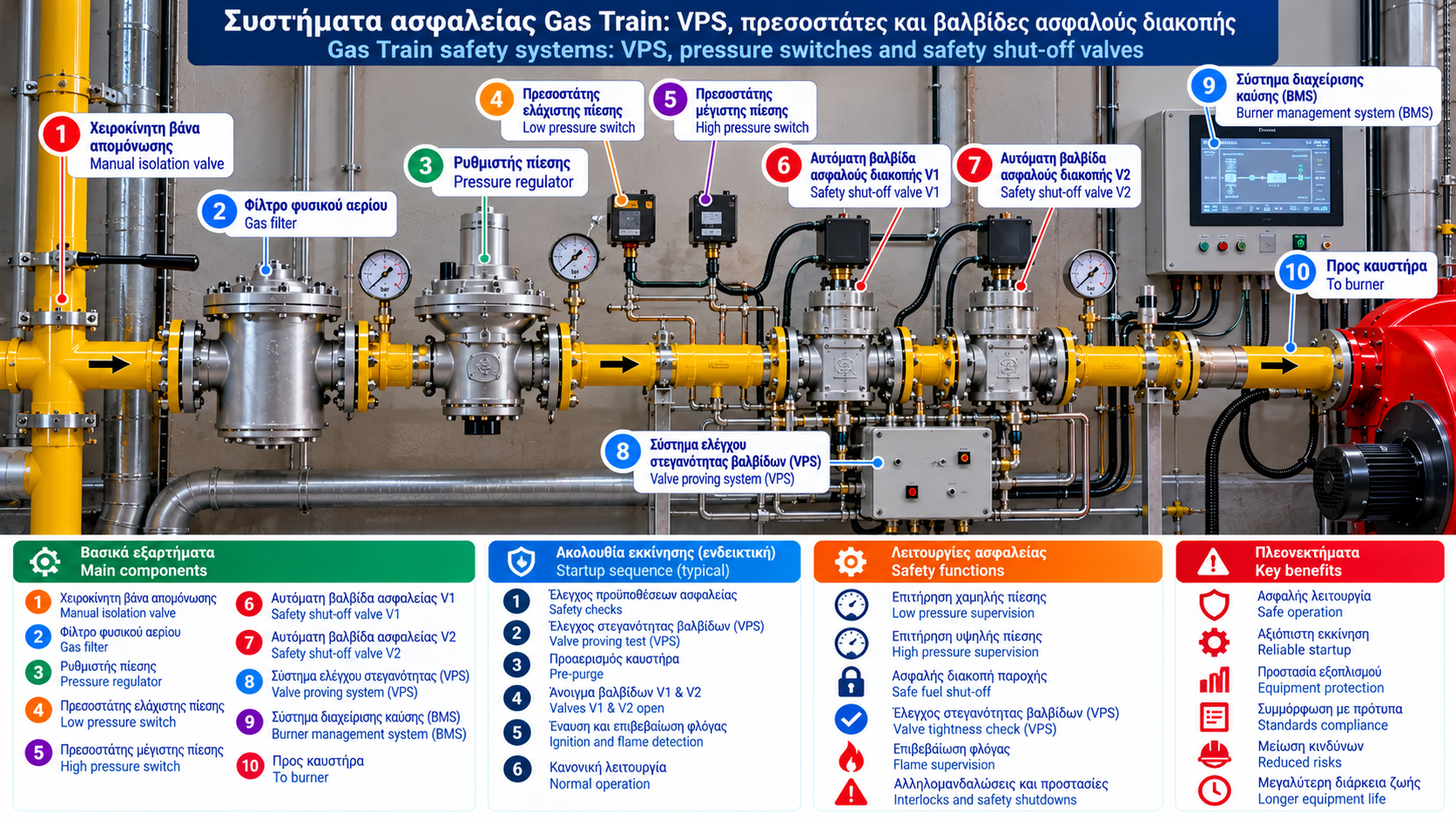
Gas Train Safety Systems: VPS, Pressure Switches and Safety Shut-Off Valves
Safe operation of an industrial natural gas burner depends on the coordinated performance of several protective devices.
A gas train is more than an assembly of pipes and valves. It forms part of the installation’s combustion safety system, controlling fuel admission and enabling isolation when operating conditions are unacceptable.
Key components include the Valve Proving System (VPS), gas pressure switches, automatic safety shut-off valves and the Burner Management System (BMS).
1. Why Does a Gas Train Need Safety Systems?
Natural gas must only be admitted to the burner when the required safety conditions have been satisfied.
Potentially hazardous situations include:
Leakage through a valve that does not close tightly.
Insufficient gas pressure.
Excessive gas pressure.
Ignition failure.
Flame loss during operation.
Insufficient combustion air.
Failure of a critical component or safety interlock.
The safety system must detect specified unsafe conditions and perform the required protective action.
Safe operation depends on the overall protection architecture rather than one individual device.
2. Main Gas Train Safety Components
An industrial gas train may include:
Low gas pressure switch.
High gas pressure switch.
Two automatic safety shut-off valves in series.
Valve Proving System.
Suitable overpressure protection devices.
Pressure measurement and monitoring points.
Integration with the BMS.
The required arrangement depends on burner capacity, operating pressure, application and applicable standards.
Not every installation requires every component listed above.
3. What Is a Valve Proving System?
A Valve Proving System checks the acceptable tightness of automatic gas shut-off valves.
In a common arrangement, two automatic valves are installed in series:
Gas supply → Valve V1 → Intermediate volume → Valve V2 → Burner
The VPS evaluates pressure behavior in the space between the valves using a predefined procedure.
If the observed pressure behavior is outside the accepted limits, the test fails.
Depending on the design, a failed test may prevent burner startup and generate a fault indication.
A VPS is not a general-purpose room gas leak detector.
4. How Does Valve Proving Work?
The exact procedure depends on the VPS manufacturer and technology.
Some systems use controlled pressure changes in the intermediate volume.
Others assess pressure increase or decrease over a specified period.
The general principle includes:
Establishing the required initial pressure condition.
Monitoring pressure in the intermediate volume.
Comparing pressure behavior with acceptable limits.
Reporting a pass or fail result.
The actual sequence, test duration and thresholds must follow the approved system design.
There is no single universal procedure for all valve proving systems.
5. Why Are Two Valves Installed in Series?
Two automatic shut-off valves in series provide the required fuel isolation architecture for many applications.
They may also allow testing of the intermediate volume.
Valve specifications can differ according to system requirements.
However, installing any two valves in series does not automatically guarantee compliance.
Correct selection, certification and integration with the safety controls are essential.
6. Automatic Safety Shut-Off Valves
Automatic safety shut-off valves allow or interrupt gas flow according to commands from the control system.
In many applications, they are normally closed, meaning they remain closed without the required energizing signal.
During normal operation, the BMS permits opening only after the relevant safety prerequisites have been satisfied.
During a protective shutdown, the valves return to their designated safe state.
Closing time, valve classification and other performance requirements must be selected according to the application and applicable standards.
7. Low Gas Pressure Switch
The low gas pressure switch supervises the availability of adequate gas supply pressure.
When pressure falls below the specified threshold, the appropriate protective function may be activated.
Possible causes include:
Reduced network pressure.
Gas flow restrictions.
Contaminated gas filter.
Undersized regulator.
Excessive pressure losses.
High fuel demand.
Pressure switch activation does not identify the root cause by itself.
8. High Gas Pressure Switch
The high gas pressure switch supervises excessive pressure.
Overpressure may result from:
Incorrect settings.
Regulator failure.
Unacceptable lock-up behavior.
Transient pressure conditions.
Problems in an upstream regulation stage.
Switch location and setpoint must correspond to the installation’s engineering requirements.
A pressure switch alone is not necessarily sufficient protection against every credible overpressure scenario.
9. Pressure Switch vs Pressure Transmitter
A pressure switch primarily supervises a predefined threshold.
A pressure transmitter provides a continuous or analog pressure measurement.
For example:
Pressure switch: Acceptable or unacceptable pressure status.
Pressure transmitter: Measured pressure, such as 85 mbar.
Displaying pressure on SCADA does not automatically replace a required certified safety function.
10. What Is a Burner Management System?
The Burner Management System coordinates critical burner operating and protective sequences.
Depending on the installation, it supervises:
Startup prerequisites.
Gas pressure switch status.
Pre-purge requirements.
Valve proving, where applicable.
Ignition sequence.
Flame detection.
Required protective shutdowns.
The BMS may be implemented through a dedicated burner controller or as part of a larger certified safety system.
11. How Does the VPS Communicate with the BMS?
The VPS provides the control system with the valve proving result.
An illustrative sequence is:
Start request → Safety checks → Successful VPS test → Continuation of approved startup sequence
If the VPS test fails, startup is inhibited according to the specified control logic.
The timing of valve proving can vary.
Some systems perform the test before startup, while others use different approved sequences.
12. What Happens When the Flame Is Lost?
Flame presence is monitored by a suitable flame supervision system.
If the flame is lost during operation, the BMS must perform the required safety action.
This includes safe interruption of fuel supply according to the certified control logic.
Permitted responses, safety times and restart conditions are defined by applicable standards and manufacturer requirements.
13. What Is Safety Lockout?
Safety lockout is a protective state that may follow a specified fault.
The burner remains unavailable until the required reset procedure has been completed.
Resetting must not be used as a way to bypass a recurring problem.
Repeated lockouts require investigation by qualified personnel.
14. Useful SCADA Safety Indications
For industrial installations, useful indications include:
Signal | Description |
Gas pressure low | Low gas pressure condition |
Gas pressure high | High gas pressure condition |
VPS fault | Valve proving failure |
Gas valve command | Valve control command |
Gas valve feedback | Position confirmation, where available |
Flame detected | Flame supervision status |
Burner lockout | Protective lockout |
Burner ready | Required prerequisites satisfied |
It is important to distinguish a valve command from actual position feedback.
A command alone does not prove that a valve has physically opened or closed.
15. How Is a VPS Failure Diagnosed?
A VPS failure can have several possible causes:
Unacceptable valve tightness.
Pressure sensing device problems.
Unsuitable supply pressure.
Intermediate volume incompatible with the selected system.
Electrical or operational faults.
Problems during the proving sequence.
Diagnosis must follow the fault code, technical documentation and approved testing procedures.
The VPS must never be bypassed to continue burner operation.
16. Common Gas Train Safety Problems
Symptom | Possible Cause | Assessment |
Burner fails to start | Safety prerequisite not satisfied | Review BMS indications |
VPS fault | Valve tightness or proving issue | Specialist inspection |
Low gas pressure | Insufficient pressure or flow | Measure pressure under load |
High gas pressure | Overpressure or regulation issue | Inspect regulation system |
Flame failure | Flame loss or supervision problem | Manufacturer-based assessment |
Repeated lockout | Recurring protective condition | Analyze event history |
These are possible explanations, not confirmed diagnoses.
17. Safety Inspection and Maintenance
Periodic checks may include:
Tightness testing according to installation requirements.
Pressure switch functional verification.
Automatic shut-off valve checks.
VPS testing.
Flame supervision testing.
Verification of critical safety interlocks.
Review of fault records.
Inspection of electrical connections.
Inspection frequency and procedures depend on manufacturer instructions, engineering design and applicable requirements.
All work must be carried out by authorized and competent personnel.
18. Relevant Technical Standards
Depending on the installation, relevant references include:
EN 161: Automatic shut-off valves for gas burners and appliances.
EN 1643: Valve proving systems for automatic shut-off valves.
EN 1854: Pressure sensing devices for gas burners and appliances.
EN 676: Automatic forced draught burners for gaseous fuels.
EN 298: Automatic burner control systems for gas or liquid fuel burners and appliances.
EN 14382: Gas safety shut-off devices for pressure regulating installations, within its scope.
The current edition and applicability of each standard must be verified for the specific installation.
Conclusion
Gas train safety systems are essential for reliable industrial natural gas burner operation.
The VPS checks the acceptable tightness of automatic valves, pressure switches supervise critical pressure limits and safety shut-off valves isolate the fuel supply when required.
The BMS coordinates these functions according to the approved safety logic.
Correct equipment selection, interlock verification and planned maintenance are essential for reducing operational risks.