
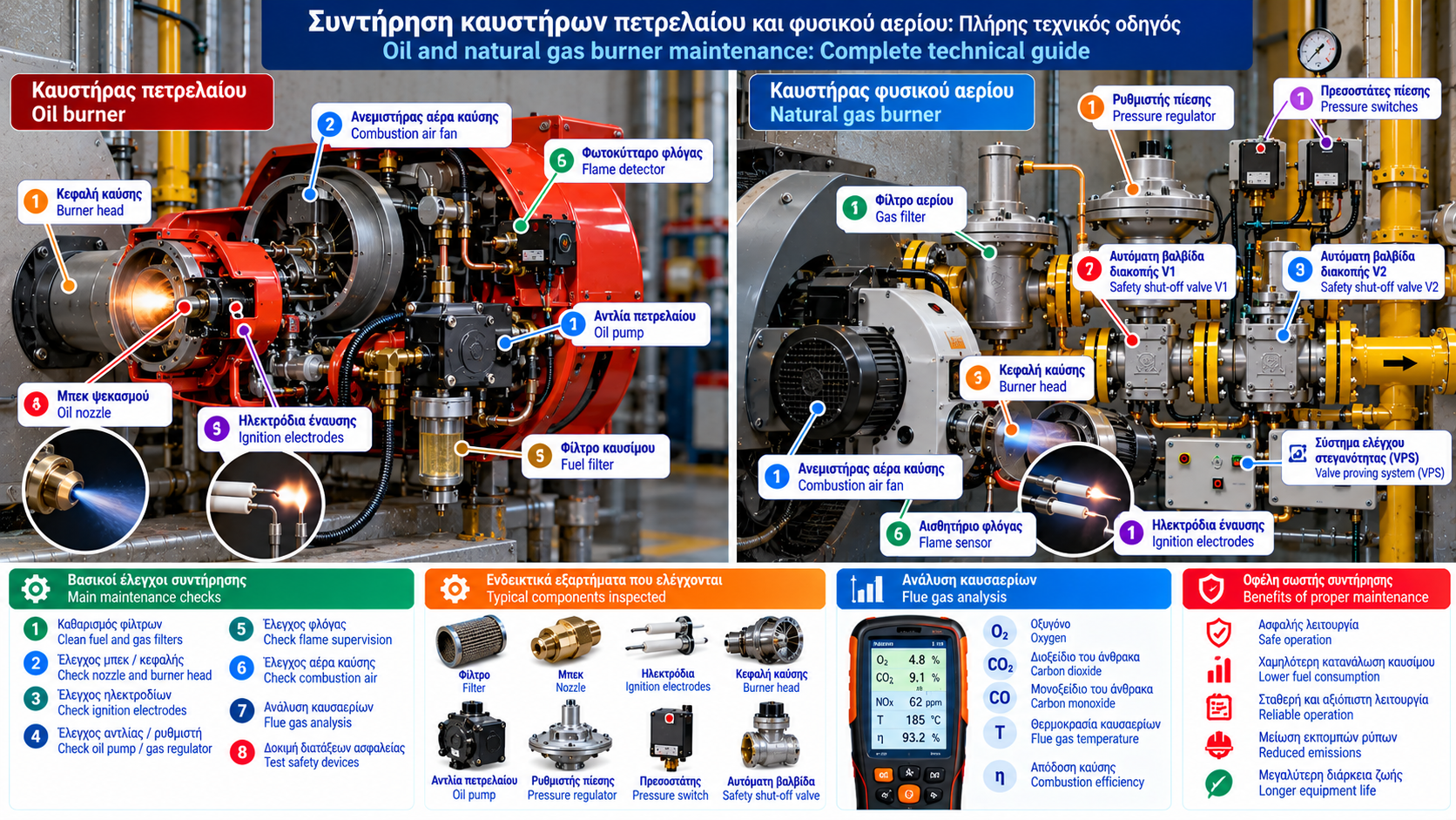
Oil and Natural Gas Burner Maintenance: Complete Technical Guide
Proper maintenance of an oil or natural gas burner is essential for safe, reliable and energy-efficient operation in heating and industrial thermal systems.
A burner operating without systematic inspection may develop increased fuel consumption, unstable flames, elevated carbon monoxide (CO) emissions, ignition difficulties and unplanned shutdowns.
Burner maintenance involves much more than cleaning. It includes mechanical and electrical inspection, fuel supply assessment, safety system verification and combustion performance evaluation using appropriate instruments.
1. Why Is Burner Maintenance Important?
Burner maintenance serves four main objectives:
Safety: Reducing risks associated with fuel leaks, incomplete combustion and protective system failures.
Energy efficiency: Maintaining suitable combustion conditions and limiting unnecessary losses.
Reliability: Reducing unplanned shutdowns.
Service life: Identifying wear and component deterioration before serious failures develop.
Maintenance should be a documented technical process supported by measurements, not simply a cleaning operation.
2. Main Components of an Oil Burner
A typical pressure-atomizing oil burner may include:
Electric motor.
Combustion air fan.
Oil pump.
Fuel filter.
Solenoid valve.
Oil atomizing nozzle.
Ignition electrodes.
Ignition transformer or electronic ignition unit.
Photocell or other flame detector.
Burner head and air diffuser.
Burner control unit.
The exact arrangement depends on burner design, manufacturer and capacity.
3. Main Components of a Natural Gas Burner
A forced-draught natural gas burner commonly includes:
Electric motor and combustion air fan.
Combustion air control mechanism.
Burner head.
Ignition electrodes.
Flame supervision device.
Burner control unit.
Air–fuel ratio control equipment, where applicable.
The gas supply assembly may include a gas filter, pressure regulator, pressure switches, automatic shut-off valves and a valve proving system.
The required arrangement depends on the application and safety requirements.
4. Preparation Before Maintenance
Before intervention, risks must be assessed and approved isolation procedures applied.
Key precautions include:
Authorization of competent personnel.
Review of manufacturer instructions.
Safe isolation of electrical and fuel supplies where required.
Prevention of unintended restart.
Assessment of hot surfaces.
Use of appropriate personal protective equipment.
Adequate ventilation.
Industrial facilities should apply relevant energy isolation procedures, including Lockout/Tagout where required.
Safety devices must never be bypassed to perform maintenance or testing.
5. Oil Burner Maintenance
Fuel filter inspection
Fuel filters capture contaminants that could affect the pump and nozzle.
Inspection should assess filter condition and identify whether replacement is required.
Oil pump inspection
The pump provides the pressure needed for oil atomization.
Checks may include:
Operating pressure.
Seal condition.
Leakage indications.
Mechanical operation.
Compatibility with the fuel supply system.
Pump pressure must not be changed arbitrarily because it affects nozzle flow.
Oil nozzle inspection
The nozzle determines important spray characteristics:
Nominal flow rate.
Spray angle.
Spray pattern.
A worn or unsuitable nozzle may cause poor atomization, unstable combustion and increased emissions.
Replacement must follow burner and boiler specifications.
6. Ignition Electrode Inspection
Ignition electrodes generate the spark required to ignite the fuel.
Inspection includes:
Physical condition.
Deposits and contamination.
Insulator condition.
Position according to manufacturer specifications.
Cable and connection condition.
Electrode spacing and geometry are manufacturer-specific.
No single electrode setting applies to every burner.
7. Natural Gas Burner Maintenance
Gas burner maintenance requires particular attention to fuel supply and protective devices.
Typical checks include:
Gas filter condition.
Gas supply pressure at designated measurement points.
Pressure regulator performance.
Pressure switch operation.
Automatic shut-off valves.
Valve proving system, where installed.
Burner head condition.
Ignition and flame supervision systems.
Tightness testing and protective function verification must follow approved procedures.
8. Combustion Air Fan Inspection
The combustion air fan supplies the air required for fuel combustion.
Deposits on the impeller or restrictions in air passages can affect airflow.
Inspection may cover:
Impeller condition.
Air inlet cleanliness.
Mechanical wear.
Abnormal vibration.
Air control mechanisms.
Motor condition.
Combustion performance must be verified after work that could affect airflow.
9. Burner Head Inspection
The burner head influences fuel–air mixing and flame stability.
Potential problems include:
Deposits.
Thermal deformation.
Corrosion.
Diffuser wear.
Incorrect component positioning.
Burner head geometry must not be modified without manufacturer guidance.
10. Flame Supervision System Inspection
Flame supervision is a critical safety function.
Depending on the burner, the system may use:
Photocells.
Ultraviolet flame detectors.
Flame ionization electrodes.
Other suitable sensing technologies.
Maintenance may include sensor inspection, permitted cleaning and verification of required operation.
Flame failure testing must be performed by competent personnel using approved procedures.
11. Why Is Flue Gas Analysis Necessary?
Visual flame appearance alone cannot establish combustion quality.
A suitable flue gas analyzer may measure:
Oxygen (O₂).
Carbon monoxide (CO).
Flue gas temperature.
Combustion air temperature.
Draught or differential pressure, depending on instrument capability.
It may also calculate CO₂, excess air and estimated combustion efficiency based on instrument configuration.
Calculated combustion efficiency is not necessarily equivalent to the boiler’s overall seasonal efficiency.
12. Understanding Oxygen Measurements
Oxygen concentration in flue gases is related to excess combustion air.
Excessively high O₂ may indicate unnecessary combustion air, but it can also be affected by air entering the flue gas system downstream of the combustion chamber.
Very low O₂ may indicate insufficient air margin and increased risk of incomplete combustion.
Suitable oxygen levels depend on fuel type, burner design, load, boiler configuration and manufacturer requirements.
There is no universal optimum O₂ setting for all burners.
13. What Does Carbon Monoxide Indicate?
Carbon monoxide is an important indicator of incomplete combustion.
Elevated CO may be associated with:
Insufficient combustion air.
Poor fuel–air mixing.
Unstable flame.
Inadequate oil atomization.
Burner head problems.
Unfavorable operating conditions.
Interpretation must distinguish actual measured concentrations from values corrected to a specified oxygen reference.
Reducing oxygen without monitoring CO and other combustion parameters can be dangerous.
14. Flue Gas Temperature Assessment
Flue gas temperature depends on:
Burner firing rate.
Boiler heat transfer.
Excess combustion air.
Heat exchanger surface condition.
System operating temperature.
An increase in flue gas temperature under comparable conditions may indicate deterioration in heat transfer.
However, temperature must be assessed in relation to boiler design and any requirements to avoid unwanted condensation.
15. Smoke Testing for Oil Burners
For applicable oil-fired systems, smoke or soot measurements provide useful combustion information.
Increased soot formation may be associated with:
Poor atomization.
Insufficient combustion air.
Inadequate mixing.
Nozzle problems.
Incorrect operating conditions.
Assessment should use a suitable test method and follow installation requirements.
16. Final Combustion Verification
After maintenance, burner performance must be verified under the specified operating conditions.
Where applicable, assessment may cover:
Startup conditions.
Flame stability.
Minimum firing rate.
Intermediate firing rate.
Maximum firing rate.
Load transition behavior.
O₂, CO and flue gas temperature.
Critical safety functions.
Final adjustments must follow manufacturer instructions, emissions requirements and applicable safety rules.
17. How Often Should Burners Be Serviced?
Maintenance frequency depends on:
Burner type.
Fuel.
Operating hours.
Installation environment.
Process criticality.
Manufacturer instructions.
Applicable regulatory requirements.
Residential systems must follow the required periodic inspection schedule.
Industrial burners operating continuously may require more frequent inspection of specific components.
Annual maintenance alone is not necessarily sufficient for every industrial installation.
18. Example Burner Maintenance Record
Parameter | Record |
Manufacturer / model | Equipment identification |
Fuel | Oil / natural gas |
Maintenance date | Inspection date |
Operating hours | Meter reading |
Fuel pressure | Measured value and unit |
O₂ | % |
CO | ppm, with reference conditions |
Flue gas temperature | °C |
Combustion air temperature | °C |
Smoke number | Where applicable |
Safety checks | Test results |
Remarks | Findings and corrective actions |
Measurements should also identify burner load and relevant operating conditions.
19. Common Maintenance Mistakes
Important mistakes to avoid include:
Installing incompatible replacement components.
Adjusting combustion without suitable instruments.
Evaluating flame appearance alone.
Ignoring elevated CO.
Changing fuel pressure without technical justification.
Bypassing pressure switches or safety systems.
Failing to verify operation after maintenance.
Keeping no measurement records.
Maintenance quality should be demonstrated through documented post-maintenance system condition.
20. Relevant Technical Standards
Depending on the equipment, relevant references include:
EN 267: Automatic forced draught burners for liquid fuels.
EN 676: Automatic forced draught burners for gaseous fuels.
EN 298: Automatic burner control systems for gas or liquid fuel burners and appliances.
EN 161: Automatic shut-off valves for gas burners and appliances.
EN 1643: Valve proving systems for automatic shut-off valves.
EN 1854: Pressure sensing devices for gas burners and appliances.
The current edition and applicability of each standard must be verified for the specific installation.
Conclusion
Oil and natural gas burner maintenance is a comprehensive technical process combining mechanical inspection, fuel supply assessment, safety system verification and flue gas analysis.
Effective maintenance is not limited to restoring burner operation. It aims to preserve safety, reliability and energy efficiency.
Final adjustment and verification must be performed by qualified personnel according to manufacturer instructions and applicable requirements.