
Radiator Connections: One-Pipe, Two-Pipe and Hydronic Installation
Correct radiator connections are essential for heat output, even room heating and reliable hydronic system operation.
Even a properly sized radiator may fail to deliver its required heat output when water flow is insufficient, the connection arrangement does not comply with manufacturer requirements or the system has not been hydraulically balanced.
The two main piping distribution arrangements are the two-pipe system and the one-pipe system. Individual radiators may also feature different connection arrangements, including side, diagonal and bottom connections.
It is important to distinguish between the overall piping distribution system and the connection arrangement of an individual radiator.
1. How Does Water Circulate Through Radiators?
In a typical closed hydronic heating system, the heat source warms the water and a circulation pump provides the pressure difference required for flow.
Water reaches the radiators, transfers thermal energy to the rooms and returns to the heat source.
The main concepts are:
Supply: The piping that carries warmer water toward the radiators.
Return: The piping that carries water back to the heat source.
Flow rate: The quantity of water passing through a circuit per unit time.
Differential pressure: The pressure difference driving circulation.
Hydraulic resistance: Resistance to flow created by pipes, fittings, valves and radiators.
Proper operation requires suitable flow distribution to each radiator.
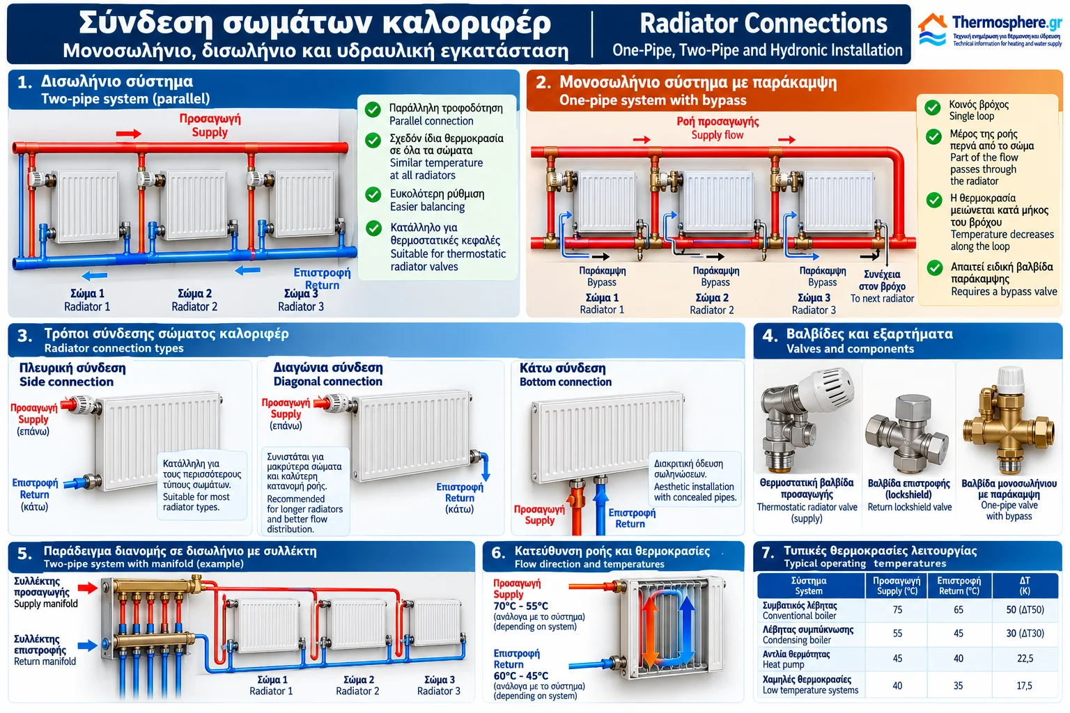
2. What Is a Two-Pipe Heating System?
A two-pipe system uses two main piping networks:
A supply network.
A return network.
Each radiator is connected hydraulically between the supply and return.
The radiators operate as parallel branches.
Water entering one radiator does not need to pass through the other radiators first.
Main Advantages
Independent radiator control.
Easier integration of thermostatic radiator valves.
Greater flexibility for hydraulic balancing.
Flexible radiator sizing.
Support for different heating zones.
Technical Consideration
Parallel connection does not automatically guarantee equal water flow.
Flow distribution depends on the hydraulic resistance of individual branches and the available differential pressure.
3. How Does a Two-Pipe Network Work?
Consider three radiators.
The main supply pipe feeds all three.
Each radiator receives part of the circulating water flow, and the outlet water enters the return network.
In a correctly designed installation, the supply temperatures reaching different radiators may be relatively similar.
However, pipe heat losses and operating differences can occur.
Actual radiator flow depends on valve settings and branch hydraulic resistance.
4. Two-Pipe Heating With Manifolds
A common variation uses supply and return manifolds.
A separate pair of pipes connects each radiator or heating circuit to the manifolds.
Advantages
Organised pipe distribution.
Individual circuit isolation.
Easier circuit identification.
Flow adjustment where suitable manifold equipment is installed.
Limitations
A manifold does not eliminate the need to calculate flow rates, pipe diameters and pressure losses.
5. What Is a One-Pipe Heating System?
In a one-pipe system, radiators are supplied from a common distribution loop.
In many residential one-pipe installations, each radiator connects through a special bypass valve or fitting.
Part of the loop flow passes through the radiator while the remaining flow continues through the bypass.
Water leaving the radiator mixes with the loop flow before reaching downstream radiators.
Important: A typical one-pipe system with bypasses does not force the entire loop flow through every radiator in sequence.
True series arrangements without bypasses also exist, but their hydraulic behaviour is different.
6. How Does the Bypass Work?
A one-pipe radiator valve distributes flow between:
The radiator branch.
The bypass path continuing around the loop.
The distribution ratio depends on valve design, adjustment and hydraulic conditions.
When radiator flow is reduced or interrupted, the bypass can allow circulation to continue toward downstream radiators.
This requires the correct valve and installation arrangement.
7. Why Does Water Temperature Decrease Along a One-Pipe Loop?
As radiators release heat into rooms, the water temperature along the loop generally decreases.
A radiator located farther downstream may therefore receive cooler water than an upstream radiator.
This affects available heat output.
Sizing must consider:
Radiator sequence.
Individual radiator heat outputs.
Loop flow rate.
Flow diversion through each radiator.
Expected temperature reduction.
It is incorrect to assume that every radiator in a one-pipe loop receives water at the same temperature.
8. One-Pipe vs Two-Pipe Systems
Feature | Two-Pipe System | One-Pipe System With Bypass |
|---|---|---|
Distribution | Parallel branches | Common loop |
Radiator supply | Main supply network | Successive loop connection points |
Inlet temperature | Generally relatively uniform | May decrease downstream |
Independent control | Usually easier | Requires suitable bypass valve |
Balancing | Individual branches | Loops and radiator branches |
Sizing | Branch-based | Whole-loop conditions |
Both systems can operate effectively when correctly designed.
9. Side Radiator Connection
With a side connection, the supply and return ports are located on the same side of the radiator.
In many conventional arrangements, the supply enters the upper connection and the return leaves through the lower connection.
This arrangement is widely used in panel and sectional radiators.
Its suitability depends on:
Radiator length.
Internal geometry.
Flow direction.
Manufacturer instructions.
Connections must not be reversed without verifying compatibility.
10. Diagonal Radiator Connection
With a diagonal connection, supply and return are located on opposite sides.
A common arrangement is:
Supply at the upper left.
Return at the lower right.
A mirrored arrangement may also be suitable where permitted.
Diagonal connections can help distribute flow across longer radiators.
However, actual performance and the recommended arrangement must be verified using manufacturer data.
11. Bottom Radiator Connection
Many modern radiators feature bottom connection ports.
Some models have closely spaced bottom ports designed for a dedicated connection valve set.
Bottom connections can provide:
Less visible pipework.
Cleaner installation appearance.
Compatibility with specific distribution arrangements.
Supply and Return Orientation
Many radiators with integrated valve mechanisms require a particular supply and return orientation.
Incorrect connections can cause noise, valve malfunction or reduced performance.
Port positions are not universal and must be confirmed from the specific product documentation.
12. Radiators With Integrated Thermostatic Valves
Some panel radiators include a factory-fitted thermostatic valve body.
The thermostatic head is mounted in the designated position.
The valve regulates radiator water flow according to the temperature sensed by the head.
Many designs also support flow presetting.
Presetting should be based on the required flow and available differential pressure.
13. Supply Valves and Return Lockshield Valves
A typical radiator installation may include:
Supply Valve or Thermostatic Radiator Valve
Allows flow adjustment or shutoff.
Return Lockshield Valve
May provide isolation and hydraulic adjustment, depending on its design.
The function and location of each valve depend on the connection arrangement.
Uncontrolled adjustment can disturb hydraulic balancing throughout the system.
14. What Is Hydraulic Balancing?
Hydraulic balancing is the process of adjusting water flows so that each radiator receives the required amount.
Without balancing, branches with lower resistance may receive excessive flow.
More distant or hydraulically demanding circuits may receive insufficient flow.
Balancing may involve:
Presettable thermostatic valves.
Balancing valves.
Suitable lockshield valves.
Differential pressure controllers.
Other approved hydraulic components.
Correct adjustment requires flow and pressure information.
15. Calculating Radiator Water Flow
Water flow can be estimated from the required heat transfer and supply-to-return temperature drop.
For water at typical heating temperatures:
Q(W) ≈ 1.163 × V̇(L/h) × ΔT_water(K)
Where:
Q is thermal power.
V̇ is volumetric water flow.
ΔT_water is the water temperature drop across the radiator.
For a radiator delivering 1,500 W with a design temperature drop of 10 K:
V̇ = 1,500 / (1.163 × 10)
V̇ ≈ 129 L/h
This is a design flow estimate for the specified heat transfer and temperature drop.
16. Pressure Losses in the Heating Network
Water circulation produces pressure losses due to friction and local resistance.
These depend on:
Pipe length.
Internal pipe diameter.
Flow rate.
Material and roughness.
Bends and fittings.
Valves.
Radiator characteristics.
The circulation pump must provide the required flow at the pressure differential needed by the designed network.
Increasing pump speed is not a universal solution to poor flow distribution.
17. Radiator Connections With Heat Pumps
Correct hydraulic distribution is especially important in heat pump installations.
Lower supply temperatures often require larger radiator heat transfer areas.
Additional considerations include:
Required system water flow.
Heat pump minimum flow requirements.
Pressure losses.
Thermostatic valve operation.
Maintaining suitable circulation during special operating modes.
Minimum system water volume requirements where applicable.
Hydraulic separation and buffer tanks are not automatically required in every installation.
Their necessity depends on engineering design and manufacturer instructions.
18. Radiator Connections With Condensing Boilers
In condensing boiler systems, lower return water temperatures generally favour flue gas condensation and heat recovery.
Correct radiator selection and hydraulic balancing can support operation at suitable water temperatures.
However, hydraulic adjustments must maintain adequate circulation and comply with boiler operating limits.
Excessively reducing water flow is not, by itself, an efficiency improvement strategy.
19. Radiator Air Venting
Air trapped inside a radiator can interfere with water circulation and reduce heat output.
Radiators therefore generally include an air vent at an appropriate location.
Possible symptoms of trapped air include:
A cold upper radiator section.
Flow noises.
Reduced or uneven heating.
Similar symptoms may also result from insufficient flow or other faults.
Air venting must follow equipment instructions and account for system pressure and water temperature.
20. Common Radiator Connection Mistakes
Reversed Supply and Return
This may cause problems in radiators with specific internal arrangements or integrated valves.
Incorrect Valve in a One-Pipe System
This can interfere with circulation throughout the loop.
Missing Hydraulic Balancing
Some radiators may receive excessive flow while others remain underheated.
Undersized Pipes
Small pipe diameters can create excessive pressure losses.
Incorrect Thermostatic Head Position
Poor positioning can cause inaccurate room temperature control.
Inadequate Mechanical Support
This can create mechanical stress and safety concerns.
Missing Leak Testing
Leaks may develop after commissioning if appropriate testing is omitted.
21. Checks Before Commissioning
After installation, qualified personnel should perform the required checks.
These may include:
Verification of supply and return orientation.
Confirmation of valve suitability.
Inspection of mechanical supports.
Leak testing according to specifications.
Filling and proper air venting.
Operating pressure checks.
Circulation verification.
Hydraulic balancing.
Heat output assessment.
Documentation of final settings.
All procedures must follow manufacturer instructions and applicable technical requirements.
22. Which Connection Arrangement Is Best?
No single arrangement is ideal for every building.
Two-pipe systems provide flexibility and individual radiator supply through parallel branches.
One-pipe systems can also perform effectively when loops, bypass valves and operating temperatures are correctly designed.
Side, diagonal and bottom radiator connections should be selected according to radiator design, pipe layout and manufacturer requirements.
The most important consideration is not simply the number of pipes, but ensuring that every radiator receives the required water flow and delivers its intended heat output.
Conclusion
Correct radiator connections are part of the overall hydraulic design of a heating installation.
One-pipe and two-pipe systems have different operating characteristics, while side, diagonal and bottom connections describe the port arrangement of individual radiators.
Suitable valve selection, correct flow calculations and hydraulic balancing are essential for even heating and reliable operation.
A radiator performs correctly only when proper thermal sizing is combined with suitable hydraulic connections and water flow.
This article is intended for technical information and is not an installation drawing. Component selection, connections and testing must be performed by qualified personnel according to engineering design and manufacturer instructions.
Thermosphere.gr — Technical information for heating and water supply.