
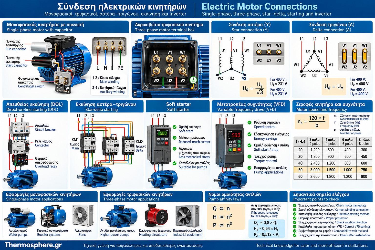
Electric Motor Connections: Complete Guide to Single-Phase, Three-Phase, Star–Delta Starting and VFDs
Correct electrical connections are essential for the safe starting, reliable operation and service life of an electric motor.
Two motors with similar rated power may require completely different connection arrangements. The appropriate method depends on the electrical supply, winding design, nameplate information, starting torque, mechanical load and control requirements.
Water supply and heating installations commonly use single-phase motors with capacitors, three-phase induction motors, electronically controlled pumps and variable-speed circulators.
The main starting methods include direct-on-line starting, reduced-voltage starting, star–delta starting, electronic soft starters and variable frequency drives.
This guide examines the operating principles of each method, their differences, advantages and limitations, as well as the main criteria for selecting a suitable motor starting system.
Important: The explanations and electrical relationships in this article are educational. They are not wiring instructions for a particular motor. Actual connections must follow the manufacturer’s documentation and be carried out by appropriately qualified and licensed professionals.
1. What Does Connecting an Electric Motor Involve?
Connecting an electric motor involves configuring the electrical circuits required for its supply, starting, operation and protection.
It is not limited to attaching the supply conductors.
It also involves:
Selecting the correct operating voltage.
Configuring motor winding connections.
Choosing the starting method.
Controlling the direction of rotation.
Providing protection against electrical faults.
Controlling rotational speed, where required.
Installing control and automation equipment.
Providing protective earthing.
A properly designed system must allow the motor to develop the required torque without exceeding its permissible electrical and thermal limits.
2. What Should Be Checked Before Connecting a Motor?
The first step is to examine the motor nameplate and the manufacturer’s technical documentation.
Essential Information
Parameter | What It Indicates |
Rated voltage | Electrical supply for which the motor is designed |
Frequency | Rated operating frequency |
Rated current | Current under specified operating conditions |
Power in kW | Usually rated mechanical output power |
Speed in rpm | Rated rotational speed |
Δ / Y | Permitted winding configurations, where applicable |
cosφ | Power factor |
Duty rating | Intended operating cycle |
IP rating | Enclosure protection |
Insulation thermal class | Thermal characteristics of the insulation system |
Why Is Motor Power Alone Insufficient?
Power does not determine the correct electrical connection.
A 3 kW motor may have different voltage, current and starting requirements from another motor with the same rated power.
The nameplate and technical manual must take precedence over general assumptions.
3. Connecting Single-Phase Electric Motors
Single-phase motors are used in many small water pumps, pressure booster systems and auxiliary installations.
Typical single-phase induction motors include:
A main winding.
An auxiliary winding.
A system that creates an appropriate phase difference.
One or more capacitors in many designs.
Why Is an Auxiliary Circuit Necessary?
Supplying only the main winding of a typical single-phase induction motor does not, by itself, produce sufficient starting torque.
An auxiliary circuit helps establish the conditions required for starting.
The precise arrangement depends on the motor’s construction.
4. Starting Capacitors and Run Capacitors
Capacitors are used in certain single-phase motors to create a phase difference between winding currents.
Starting Capacitor
A starting capacitor operates during the starting period in motors designed for this arrangement.
It is normally disconnected after starting through a suitable switching mechanism.
Run Capacitor
A run capacitor remains connected during operation in motors designed for continuous capacitor operation.
Main Differences
Characteristic | Starting Capacitor | Run Capacitor |
Operating period | Usually temporary | Continuous, where specified |
Main purpose | Improve starting characteristics | Maintain the required phase relationship during operation |
Construction | Suitable for the specified starting duty | Suitable for continuous operation |
Selection | According to manufacturer specifications | According to manufacturer specifications |
Important Safety Warning
A capacitor must not be replaced arbitrarily based only on its physical appearance.
Capacitance, rated voltage, capacitor type, duty classification and manufacturer requirements must all be verified.
Capacitors can retain dangerous electrical energy even after the power supply has been disconnected.
5. Single-Phase Motors in Water Pumps
Single-phase capacitor motors are frequently found in domestic water pumps and small pressure booster systems.
Important Operating Characteristics
Required starting torque.
Starting frequency.
Hydraulic load.
Rated current.
Thermal protection.
Correct supply voltage.
Why Does Starting Frequency Matter?
Repeated starts cause thermal stress in motor windings.
In a pressure booster system, excessive starting frequency may be associated with incorrect settings, pressure vessel problems or other system operating issues.
Troubleshooting must consider both the electrical and hydraulic systems.
6. Connecting Three-Phase Electric Motors
Three-phase induction motors normally contain three stator windings.
In many motors, the winding ends are brought to a terminal box, allowing different connections according to the motor’s design and nameplate.
Common Terminal Markings
U1 and U2.
V1 and V2.
W1 and W2.
These markings identify the ends of the windings.
What Determines the Connection Arrangement?
Rated winding voltage.
Supply voltage.
Intended starting method.
Manufacturer instructions.
The correct connection must not be inferred solely from the physical position of the terminals.
7. Star Connection (Y)
In a star connection, one end of each winding is connected to a common point.
The remaining ends are connected to the three supply phases.
In a balanced three-phase system:
Uphase = Uline / √3
Where:
Uphase: Voltage across each winding.
Uline: Line-to-line supply voltage.
Example
For a line voltage of 400 V:
Uphase = 400 / √3
Uphase ≈ 231 V
Therefore, with a 400 V line voltage and a star connection, each winding receives approximately 231 V.
Important
A star connection is not suitable for every motor at every supply voltage.
Suitability depends on the rated winding voltage and nameplate information.
8. Delta Connection (Δ)
In a delta connection, the three windings are connected end-to-end to form a closed circuit.
The three supply phases connect to the corresponding junction points.
In a balanced three-phase system:
Uphase = Uline
In other words, the voltage across each winding equals the line-to-line supply voltage.
Example
For a 400 V supply:
Uphase = 400 V
Each winding receives 400 V.
Why Is the Nameplate Critical?
If a winding is designed for 230 V, applying 400 V directly across it can cause severe electrical overstress.
An incorrect connection is not simply an operational error; it can destroy the motor.
9. What Do 230/400 V and 400/690 V Mean?
Dual-voltage markings on motors suitable for delta and star connections relate to the rated winding voltage.
Example: 230/400 V Δ/Y
In a typical case:
Delta (Δ): 230 V line voltage.
Star (Y): 400 V line voltage.
On a 400 V three-phase supply, this motor normally operates in star, provided the nameplate and manufacturer confirm the arrangement.
Example: 400/690 V Δ/Y
In a typical case:
Delta (Δ): 400 V line voltage.
Star (Y): 690 V line voltage.
On a 400 V supply, the motor may be designed for normal operation in delta.
Basic Principle
A 230/400 V marking does not mean the motor can be connected arbitrarily in either configuration on the same supply.
The winding connection must match the rated winding voltage.
10. Direct-On-Line Motor Starting (DOL)
Direct-on-line starting, or DOL, is one of the simplest starting methods for suitable motors.
The motor is connected to its intended supply voltage through an appropriate control and protection system.
Advantages
Relatively simple arrangement.
Wide applicability.
Limited complexity.
Broad availability of equipment.
Limitations
During starting, the motor may draw a current significantly higher than its rated current.
This can affect:
Supply voltage drop.
Mechanical stress.
Thermal performance.
Selection of protective devices.
Illustrative Example
Suppose a motor has a rated current of 10 A and a starting-current-to-rated-current ratio of 6.
Istart = 6 × 10 = 60 A
This is an illustrative value. Actual starting current depends on the motor and supply conditions.
11. Star–Delta Starting
Star–delta starting is used with suitable three-phase induction motors.
The method is based on changing the winding configuration during starting.
Operating Principle
During the initial starting stage, the windings are connected in star.
The system then changes to the intended delta connection for normal operation.
Essential Requirement
The motor must be suitable for normal delta operation at the supply line voltage.
For example, a typical 400/690 V Δ/Y motor may be suitable for star–delta starting on a 400 V supply, provided all other requirements are satisfied.
By contrast, a typical 230/400 V Δ/Y motor is not suitable for normal delta operation on a 400 V supply.
What Does It Achieve?
The reduced voltage across each winding during starting limits the starting current.
However, it also reduces the available starting torque.
12. Current and Torque During Star–Delta Starting
For the same motor and the same supply line voltage, a simplified comparison with direct starting in delta gives:
Iline,Y ≈ Iline,Δ / 3
Starting torque is approximately proportional to the square of the applied winding voltage.
Therefore:
Tstart,Y ≈ Tstart,Δ / 3
Example
Suppose direct starting in delta produces the following illustrative values:
Starting line current: 90 A.
Starting torque: 60 N·m.
Under the simplified assumptions:
Starting line current in star: approximately 30 A.
Starting torque in star: approximately 20 N·m.
Why Does This Matter?
This method is not suitable for every load.
If the required starting torque is high, the motor may struggle to accelerate sufficiently.
The transition from star to delta can also produce electrical and mechanical transients.
Actual values depend on the motor, load and starting arrangement.
13. Soft Starters
A soft starter is an electronic device used to control the starting process of suitable motors.
In common applications, it controls the voltage applied during starting.
Main Objectives
Limit starting current.
Reduce sudden mechanical stress.
Provide smoother acceleration.
Enable controlled deceleration in suitable applications.
Applications in Pumps
In certain pumping systems, properly configured soft starting or stopping can reduce undesirable hydraulic transients.
However, effectiveness depends on the characteristics of the pump and pipe network.
Limitation
A typical soft starter does not provide continuous speed control in the same way as a variable frequency drive.
After starting, the motor generally operates near the speed corresponding to the supply frequency and mechanical load.
14. What Is an Inverter or VFD?
A variable frequency drive (VFD) is an electronic system that controls the electrical supply to a suitable motor.
By varying frequency and voltage, or using more advanced control methods, it can regulate speed and torque.
Main Components
A common AC–DC–AC variable frequency drive includes:
Rectifier.
DC intermediate circuit.
Power inverter.
Electronic control system.
What Can a VFD Achieve?
Variable motor speed.
Controlled acceleration.
Controlled deceleration.
Operation adapted to load requirements.
Monitoring and diagnostic functions.
Energy savings in suitable applications.
Energy savings are not identical for every type of load.
15. How Does Frequency Affect Motor Speed?
The synchronous speed of the rotating magnetic field is given by:
ns = 120 × f / p
Where:
ns: Synchronous speed in rpm.
f: Frequency in Hz.
p: Number of poles.
Example: Four-Pole Motor
Frequency | Synchronous Speed |
20 Hz | 600 rpm |
30 Hz | 900 rpm |
40 Hz | 1,200 rpm |
50 Hz | 1,500 rpm |
60 Hz | 1,800 rpm |
The actual speed of an induction motor differs from synchronous speed because of slip.
Important Clarification
The ability to operate at different frequencies does not mean every motor can run at any speed without limitations.
The following must be considered:
Cooling.
Permissible torque.
Mechanical limits.
Insulation characteristics.
Suitability for VFD operation.
Manufacturer instructions.
16. V/f Control and Vector Control
Variable frequency drives can use different control strategies.
V/f Control
The basic principle involves adjusting voltage appropriately in relation to frequency.
It is used in many applications that do not require particularly precise dynamic torque control.
Vector Control
Vector control uses mathematical models and measured or estimated electrical quantities to provide more advanced control of electromagnetic torque.
Comparison
Characteristic | V/f Control | Vector Control |
Basic principle | Voltage-to-frequency relationship | Control of electromagnetic quantities |
Complexity | Usually lower | Usually higher |
Dynamic response | Depends on application | Potentially improved response |
Configuration | Often simpler | May require more motor data |
The appropriate choice depends on the load and system requirements.
17. VFDs in Water Pumps and Booster Systems
Variable frequency drives are widely used in pumping systems with changing demand.
Example Application
A pressure booster system may include:
Pressure sensor.
Electronic controller.
VFD.
Electric motor.
Pump.
The controller adjusts motor speed according to the required operating conditions.
Potential Benefits
Flow adjustment.
Reduced unnecessary operation at high speed.
Smoother starting.
Pressure regulation.
Energy savings under suitable conditions.
What Should Be Considered?
Minimum operating speed, motor cooling, hydraulic limits and pump characteristics must be taken into account.
Not every pump is suitable for unrestricted speed variation.
18. Pump Affinity Laws and Energy Savings
For the same centrifugal pump, under suitable assumptions and at corresponding operating points, the pump affinity laws can be expressed approximately as:
Q ∝ n
H ∝ n²
P ∝ n³
Where:
Q: Flow rate.
H: Pump head.
P: Required power.
n: Rotational speed.
Worked Example
Suppose the rotational speed is reduced to 80% of its original value:
n₂/n₁ = 0.8
Then, approximately:
Q₂/Q₁ ≈ 0.8
H₂/H₁ ≈ 0.64
P₂/P₁ ≈ 0.512
In other words, the theoretical required power may decrease to approximately 51.2% of its initial value.
Important Limitation
These relationships do not guarantee identical savings in every real installation.
Actual performance depends on:
Pump characteristic curve.
System characteristic curve.
Static head.
Pump efficiency.
Motor efficiency.
VFD losses.
Minimum permissible operating limits.
19. Reversing Electric Motor Rotation
The direction of rotation is important for the correct operation of many machines.
Three-Phase Induction Motors
In suitable applications, reversing the sequence of two supply phases changes the direction of the rotating magnetic field.
Actual implementation requires appropriate control and protection arrangements.
Single-Phase Motors
Reversing rotation depends on the internal winding arrangement and the options provided by the manufacturer.
It generally cannot be achieved simply by swapping the two supply conductors.
Motors Controlled by a VFD
Rotation direction can be controlled electronically, provided the motor, drive and mechanical application permit it.
Application in Pumps
Incorrect rotation can significantly reduce pump performance or cause operating problems.
The direction must be verified according to the manufacturer’s instructions.
20. Choosing a Motor Starting Method
No single starting method is suitable for every application.
Method | Main Advantage | Main Limitation |
Direct-on-line (DOL) | Simplicity | High starting current in many applications |
Star–delta | Reduced starting current | Significantly reduced starting torque |
Soft starter | Smoother starting | Usually no continuous speed control |
VFD / inverter | Speed and torque control | Greater complexity and specific requirements |
Single-phase capacitor arrangement | Suitable starting for specific single-phase motors | Depends on motor design and capacitor specification |
Selection Criteria
Motor power.
Rated and starting current.
Required starting torque.
Load inertia.
Starting frequency.
Electrical supply capabilities.
Need for speed control.
Mechanical and hydraulic requirements.
Energy efficiency.
Installation and maintenance costs.
21. Common Motor Connection and Starting Errors
Error | Possible Consequence |
Incorrect Δ/Y connection | Winding overstress |
Ignoring the nameplate | Incorrect voltage or current |
Unsuitable capacitor | Starting problems and overheating |
Inappropriate DOL selection | Excessive starting current |
Unsuitable star–delta starting | Insufficient torque or switching transients |
Incorrect VFD parameters | Operating and protection problems |
Ignoring cooling at low speeds | Overheating |
Incorrect rotation direction | Reduced performance or mechanical damage |
Inadequate protection | Increased risk of motor failure |
Insufficient commissioning checks | Undetected operating problems |
Additional VFD Considerations
Using a variable frequency drive may require specific assessment of:
Electromagnetic interference.
Suitable motor cabling.
Cable length.
Overvoltage at motor terminals.
Bearing currents in certain applications.
Compatibility with protective devices.
Safe isolation and discharge of the DC intermediate circuit.
Configuration must follow the motor data and the VFD manufacturer’s instructions.
22. Frequently Asked Questions About Motor Connections and Starting
1. What Is the Difference Between Star and Delta Connections?
In star, the voltage across each winding equals the line voltage divided by √3. In delta, each winding receives the full line voltage.
2. Can a 230/400 V Motor Operate in Delta on a 400 V Supply?
For a typical motor marked 230/400 V Δ/Y, no. On a 400 V supply, the intended connection is star.
3. When Is Star–Delta Starting Used?
When the motor is suitable for normal delta operation at the supply voltage and the load can start with the reduced available torque.
4. Why Does a Single-Phase Motor Need a Capacitor?
In certain designs, the capacitor helps create the appropriate phase difference required for starting or operation.
5. What Is the Difference Between a Soft Starter and a VFD?
A soft starter mainly controls starting and, in some applications, stopping. A VFD allows continuous adjustment of frequency and motor speed.
6. Can Every Three-Phase Motor Be Connected to a VFD?
Not without evaluation. Motor suitability, insulation, cooling, electrical characteristics and manufacturer instructions must be considered.
7. Can a VFD Reduce a Pump’s Energy Consumption?
Yes, in suitable variable-load applications. Actual savings depend on the pump and hydraulic network.
8. Why Might a Motor Fail to Start with Star–Delta Starting?
One possible cause is insufficient starting torque. Other electrical or mechanical causes may also require investigation.
9. How Is the Rotation Direction of a Three-Phase Motor Reversed?
For a suitable three-phase induction motor, changing the sequence of two phases reverses the rotating magnetic field. This must be performed using an appropriate professional procedure.
10. Which Starting Method Is Best for a Water Pump?
It depends on the motor, power rating, required torque, starting frequency, electrical supply and pump operating requirements.
Conclusion
Electric motor connections and starting methods directly affect safety, reliability and operating performance.
In single-phase motors, suitable auxiliary winding and capacitor arrangements provide the intended starting characteristics.
In three-phase motors, star or delta connection is determined by the rated winding voltage and supply voltage.
Direct-on-line starting offers simplicity, while star–delta starters and soft starters can reduce specific stresses, subject to their respective limitations.
Variable frequency drives provide additional capabilities for speed control, operational management and energy optimisation, particularly in suitable pumping systems.
The correct connection method is not simply the one that makes the motor rotate. It is the one that ensures winding compatibility, sufficient torque, appropriate protection and reliable operation under the actual load.
Thermosphere.gr — Technical knowledge for safer and more efficient installations.
Important Safety Notice
This article is intended for informational and educational purposes. It is not a guide for unqualified persons to carry out electrical connections.
The installation, connection, configuration, maintenance and testing of electric motors must be performed by appropriately trained and licensed professionals.
Before any work, safe isolation procedures and verification of the absence of voltage must be carried out. For systems using VFDs, particular attention must be paid to stored energy in the DC intermediate circuit, in accordance with the manufacturer’s instructions.
Technical References and Standards
IEC 60034-1 — Rotating Electrical Machines: Rating and Performance.
IEC 60034-12 — Starting Performance of Single-Speed Three-Phase Cage Induction Motors.
IEC 60034-30-1 — Efficiency Classes of Line-Operated AC Motors.
IEC 60034-30-2 — Efficiency Classes of Variable Speed AC Motors.
IEC 61800 Series — Adjustable Speed Electrical Power Drive Systems.
IEC 61800-3 — EMC Requirements and Specific Test Methods.
IEC 61800-5-1 — Electrical, Thermal and Energy Safety Requirements.
IEC 60947-4-1 — Electromechanical Contactors and Motor-Starters.
IEC 60947-4-2 — Semiconductor Motor Controllers, Starters and Soft-Starters.
IEC 60204-1 — Safety of Machinery: Electrical Equipment of Machines.
IEC 60364 — Low-Voltage Electrical Installations.
ELOT — Hellenic Organization for Standardization: https://www.elot.gr/
IEC — International Electrotechnical Commission: https://www.iec.ch/
Note: The applicability of individual standards depends on the motor type, equipment, scope of application and currently applicable editions.