
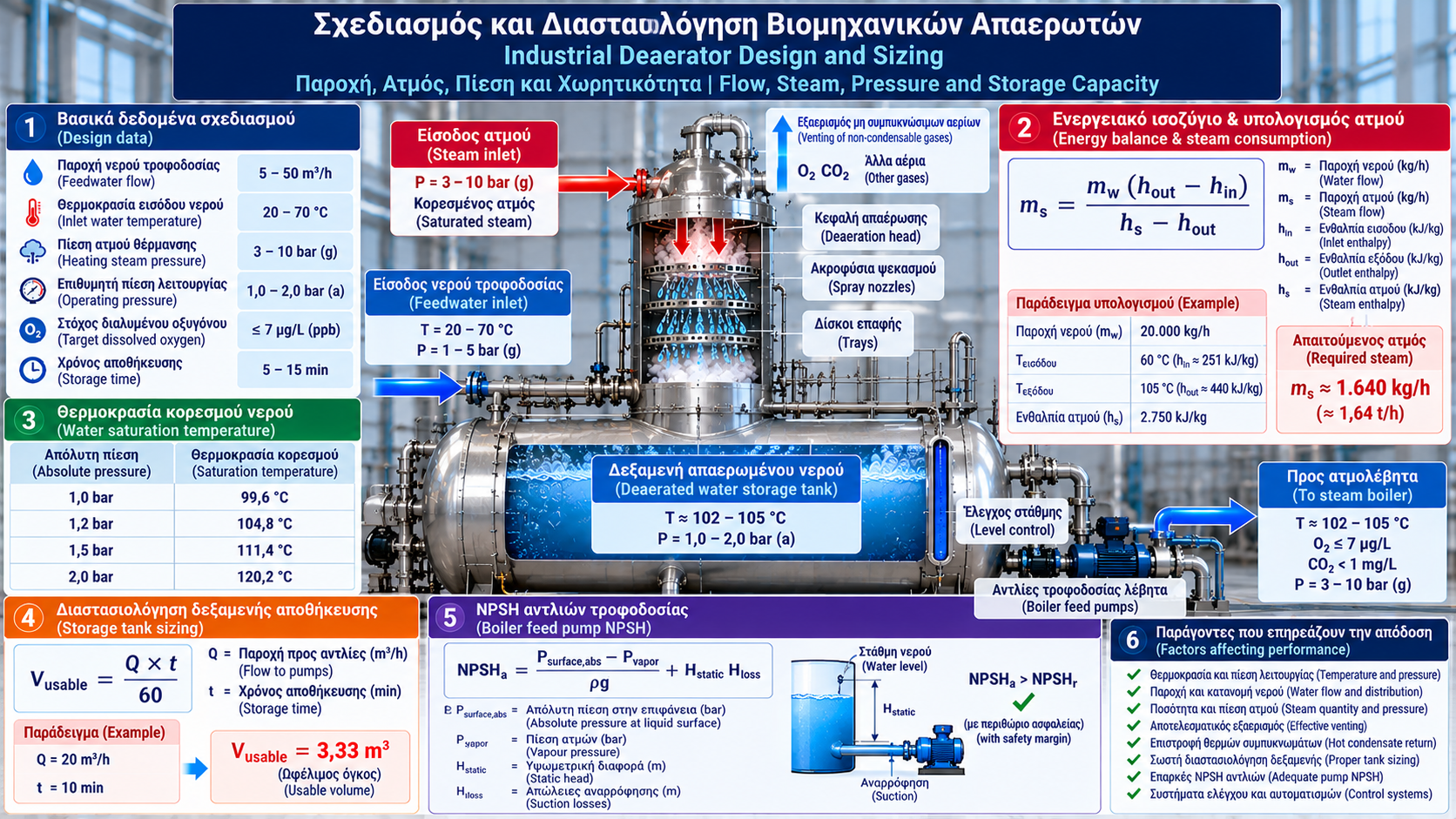
# Industrial Deaerator Design and Sizing: Flow, Steam Consumption, Pressure and Storage Capacity
## Introduction
Proper design of an industrial thermal deaerator is essential for safe and reliable steam generation.
The deaerator must provide adequate feedwater heating, effective removal of dissolved oxygen and free carbon dioxide, sufficient water storage and stable suction conditions for boiler feedwater pumps.
Deaerator sizing is not simply a matter of selecting a storage vessel. It requires an integrated assessment of hydraulic, thermal, mechanical and operational requirements.
## 1. Essential Design Data
Before selecting a deaerator, the following information should be established:
- Nominal and maximum feedwater flow.
- Minimum flow and load variations.
- Incoming water temperature.
- Condensate return percentage.
- Available steam pressure and temperature.
- Required deaerator operating pressure.
- Target dissolved oxygen concentration.
- Required water storage time.
- Boiler feedwater pump elevation.
- Applicable safety and regulatory requirements.
Design data should cover normal operating conditions and important transient scenarios.
## 2. Feedwater Flow Calculation
The required deaerator capacity is related to the overall steam system water balance.
A simplified inlet water balance is:
Qmakeup + Qcondensate = Qwater,in
Where:
Qmakeup = Makeup water flow.
Qcondensate = Returned condensate flow.
Qwater,in = Total incoming water flow.
A complete mass balance must also consider condensed heating steam, vent losses and other relevant inlet or outlet streams.
For example, if the deaerator receives 7,000 kg/h of makeup water and 13,000 kg/h of condensate, the incoming water flow is 20,000 kg/h.
This is not necessarily identical to the final boiler feedwater flow because some heating steam condenses inside the deaerator.
## 3. Operating Pressure and Temperature
Thermal deaerators generally operate with water close to the saturation temperature corresponding to the internal pressure.
Approximate pure-water saturation temperatures are:
- 1.0 bara: 99.6°C.
- 1.2 bara: 104.8°C.
- 1.5 bara: 111.4°C.
- 2.0 bara: 120.2°C.
Absolute pressure (bara) must be distinguished from gauge pressure (barg).
Operating pressure is selected based on steam availability, feedwater temperature, deaeration requirements and mechanical design.
## 4. Deaerator Energy Balance
Steam consumption can be estimated using a combined mass and energy balance.
For a simplified system without vent or heat losses:
mw × hw + ms × hs = (mw + ms) × hout
Where:
mw = Incoming water flow (kg/h).
ms = Heating steam flow (kg/h).
hw = Incoming water specific enthalpy (kJ/kg).
hs = Incoming steam specific enthalpy (kJ/kg).
hout = Outlet water specific enthalpy (kJ/kg).
Solving for steam flow:
ms = mw × (hout − hw) / (hs − hout)
This relationship assumes that the heating steam condenses into the outlet water and that no other significant inlet or outlet streams exist.
Real installations require additional terms for venting, heat losses and other streams.
## 5. Steam Consumption Example
Consider:
- Incoming water flow: 20,000 kg/h.
- Incoming water temperature: 60°C.
- Outlet temperature: approximately 105°C.
- Incoming water enthalpy: approximately 251 kJ/kg.
- Outlet water enthalpy: approximately 440 kJ/kg.
- Available steam enthalpy: 2,750 kJ/kg.
Then:
ms = 20,000 × (440 − 251) / (2,750 − 440)
ms ≈ 1,636 kg/h
The theoretical heating steam requirement is approximately 1.64 t/h.
This estimate excludes venting losses, heat losses and operating allowances.
Enthalpy values are illustrative and must be verified using suitable steam and water property data for the actual conditions.
## 6. Effect of Condensate Return
Returning hot condensate generally reduces the required heating duty.
For two water streams mixing without heat losses:
hmix = (m1 × h1 + m2 × h2) / (m1 + m2)
Where:
m1 and m2 are mass flow rates, and h1 and h2 are their respective specific enthalpies.
Using enthalpy is preferable to a simple temperature average when accurate energy calculations are required.
Potential flash steam losses and condensate quality must also be considered.
## 7. Storage Tank Sizing
The deaerated water storage tank provides an operating reserve for boiler feedwater supply.
The required usable water volume can be estimated using:
Vusable = Q × t / 60
Where:
Vusable = Usable water volume (m³).
Q = Flow to boiler feed pumps (m³/h).
t = Required storage time (minutes).
Example:
For a flow of 20 m³/h and a storage time of 10 minutes:
Vusable = 20 × 10 / 60
Vusable ≈ 3.33 m³
This represents usable water volume, not necessarily total geometric tank volume.
Final tank sizing must account for control levels, minimum operating volume, vapor space and manufacturer requirements.
## 8. Boiler Feed Pump NPSH
Proper boiler feed pump installation is critical because deaerator water is frequently close to saturation conditions.
For a simplified arrangement with the liquid level above the pump:
NPSHa = (Psurface,abs − Pvapor) / (ρg) + Hstatic − Hloss
Where:
NPSHa = Net positive suction head available (m).
Psurface,abs = Absolute pressure above the liquid surface.
Pvapor = Vapor pressure at water temperature.
ρ = Water density.
g = Gravitational acceleration.
Hstatic = Elevation difference between water surface and pump reference elevation.
Hloss = Suction line friction and minor losses.
When water is close to saturation, Psurface,abs − Pvapor may be very small.
Therefore, available NPSH depends strongly on static elevation and suction piping losses.
NPSHa must exceed the pump's required NPSHr with an appropriate margin according to manufacturer recommendations.
## 9. Vent Sizing
The venting system removes non-condensable gases.
Required vent capacity depends on:
- Incoming dissolved gas concentrations.
- Feedwater flow.
- Deaerator type.
- Operating pressure.
- Residual oxygen requirements.
- Manufacturer design.
Insufficient venting reduces deaeration efficiency.
Excessive venting increases steam losses.
Arbitrary vent flow percentages should not be applied without equipment-specific design justification.
## 10. Control Systems and Automation
An industrial deaerator may include:
- Steam pressure control.
- Water level control.
- Temperature monitoring.
- High and low level alarms.
- Overpressure protection.
- Dissolved oxygen monitoring.
- PLC or DCS integration.
Control logic should address load variations, loss of steam, loss of water supply and safe equipment conditions.
## 11. Mechanical Design and Safety
The deaerator vessel and deaeration head must be designed for specified pressure and temperature conditions.
Applicable pressure equipment codes and standards depend on installation location and equipment classification.
Within the European Union, the Pressure Equipment Directive 2014/68/EU (PED) may apply.
Final mechanical design should address:
- Design pressure and temperature.
- Construction materials.
- Corrosion and fatigue.
- Pressure relief devices.
- Supports and thermal expansion.
- Inspection and maintenance access.
- Certification requirements.
## 12. Common Sizing Mistakes
Typical sizing problems include:
- Underestimating maximum flow.
- Using an incorrect energy balance.
- Providing insufficient storage volume.
- Inadequate pump NPSH.
- Incorrect operating pressure selection.
- Insufficient venting.
- Ignoring transient loads.
- Incorrect control valve sizing.
The design must accommodate nominal operation and expected load variations.
## Conclusion
Industrial deaerator sizing requires an integrated engineering approach.
Feedwater flow, steam energy balance, operating pressure, storage capacity and available pump NPSH are closely related.
Preliminary calculations provide a useful starting point, but final equipment selection requires verification by qualified engineers and the equipment manufacturer.
Thermosphere.gr – Technical Knowledge for Professionals.