
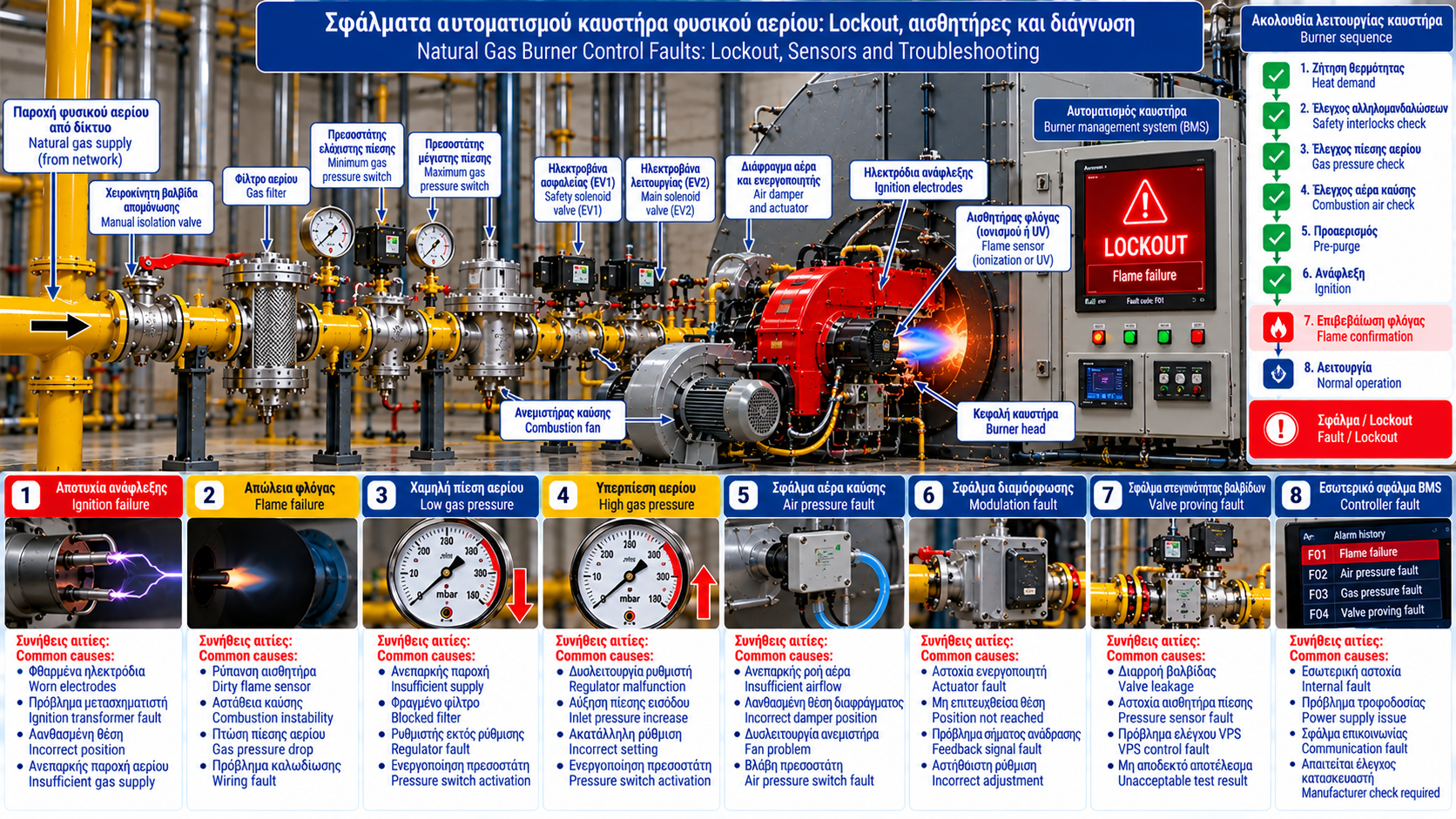
Natural Gas Burner Control Faults: Lockout, Sensors and Troubleshooting
The control system of an industrial natural gas burner does more than switch fuel on and off. It supervises startup, verifies safety conditions, monitors flame presence and shuts down the burner when unacceptable conditions occur.
A displayed fault does not always identify the underlying component failure. In many cases, it indicates the operating stage or safety condition that was not successfully verified.
Effective troubleshooting requires understanding the control sequence, reviewing relevant signals and correlating alarms with actual operating conditions.
1. What Is a Burner Management System?
A Burner Management System (BMS) manages the burner’s critical safety functions.
Depending on its design, it may supervise:
Startup permissives.
Safety interlocks.
Pre-purge.
Ignition sequence.
Fuel valve activation.
Flame establishment and continuous supervision.
Safe shutdown.
Lockout and reset conditions.
Smaller burners may use a dedicated burner controller, while larger installations may employ more complex safety architectures.
2. BMS Versus Combustion Control
The combustion control system regulates operating parameters such as firing rate and air-fuel ratio.
The BMS supervises the safety conditions and permitted operating sequence.
These functions work together but are not identical.
A demand for increased firing rate must not override an active safety shutdown condition.
3. What Does Burner Lockout Mean?
Lockout is a protective state that prevents burner restart until the required reset conditions have been satisfied.
Possible causes include ignition failure, flame supervision loss, combustion air faults, actuator position errors, valve proving failure, sensor faults and internal controller errors.
The precise response depends on the manufacturer and system configuration.
4. Lockout, Safety Shutdown and Standby
Standby: The burner is available but no active operating demand is present.
Safety shutdown: Fuel is shut off because a required condition is no longer satisfied.
Lockout: Restart is inhibited until the specified reset procedure has been completed.
Not every safety shutdown necessarily results in lockout.
5. Why a Fault Code Is Not a Complete Diagnosis
A “Flame Failure” message indicates that the required flame signal was not established or was lost.
It does not prove that the flame detector is defective.
The underlying cause may involve actual flame loss, insufficient fuel, unstable combustion, wiring faults, detector problems or related control circuits.
Fault codes must be interpreted alongside the operating stage and available recorded data.
6. Safety Interlock Faults
Interlocks verify that essential operating conditions are satisfied.
Depending on the installation, they may include boiler pressure limits, low-water protection, high-temperature limits, gas pressure switches, combustion air proving, damper position and emergency shutdown systems.
When an interlock activates, the actual condition must be investigated.
Safety contacts must never be bridged to force burner operation.
7. Gas Pressure Switch Faults
Minimum and maximum gas pressure switches can prevent startup or initiate shutdown.
Potential causes include actual pressure deviations, regulator malfunction, clogged filters, inadequate supply under load, switch faults and wiring problems.
Diagnosis must include verification of actual pressure at the specified measurement points.
8. Combustion Air Proving Faults
Fan operation alone does not prove that combustion air requirements are satisfied.
The system may use air pressure switches, pressure sensors, damper position feedback or other devices.
Possible faults include inadequate airflow, restricted intake, fan malfunction, actuator problems, missing damper position confirmation and sensor or wiring faults.
Troubleshooting must follow the manufacturer’s approved sequence.
9. Pre-Purge Faults
Pre-purge is an important safety function where specified.
The sequence may stop if required damper positions, airflow conditions, valve states or other permissives are not confirmed.
Pre-purge timing and safety conditions must never be bypassed or arbitrarily shortened.
10. Ignition Faults
An ignition fault indicates that the required flame was not confirmed within the specified time.
Possible areas of investigation include ignition transformers, electrodes, high-voltage cables, fuel admission, ignition air-fuel conditions and flame supervision.
Diagnosis must follow manufacturer instructions without unauthorized component activation.
11. Flame Supervision Faults
Flame supervision may use ionization electrodes, UV detectors or other approved technologies.
Possible problems include sensor contamination, wear, poor positioning, wiring faults, inadequate grounding where relevant, actual flame instability and electronic faults.
A visible flame does not necessarily mean that the controller has received a valid flame signal.
12. False Flame Signals
Some controllers detect unexpected flame signals during stages when no flame should be present.
This condition requires careful investigation.
Depending on detector technology, possible causes may include electrical interference, sensor faults or an actual unacceptable flame condition.
It must not automatically be dismissed as an electronic nuisance.
13. Gas Valve and Valve Proving Faults
Automatic safety shut-off valves form part of the safe fuel supply system.
The controller may supervise their operating sequence and, where specified, valve tightness testing.
Valve proving faults may be associated with internal valve leakage, pressure sensing problems, controller faults or unsuitable test conditions.
Valve proving must not be bypassed.
14. Actuator and Damper Position Faults
Modulating burners may use actuators for combustion air and fuel control.
Possible faults include failure to reach a commanded position, loss of position feedback, mechanical obstruction, electrical supply problems and control faults.
Comparing commanded and actual positions can provide valuable diagnostic information.
15. Internal Controller Faults
Some controllers detect internal memory, electronic, communication or power supply faults.
Specific codes must be interpreted using the manufacturer’s documentation.
A general “Controller Fault” message does not always prove that the entire control unit must be replaced.
16. Fault Diagnosis Table
Fault Indication | Possible Problem Area | Diagnostic Focus |
Burner Lockout | Protective shutdown state | Review code and history |
Safety Interlock Open | Unsatisfied safety condition | Identify active interlock |
Low Gas Pressure | Low pressure or monitoring fault | Verify actual pressure |
High Gas Pressure | Overpressure or monitoring fault | Assess pressure control |
Air Pressure Fault | Airflow not proven | Review air proving conditions |
Purge Failure | Incomplete purge sequence | Review operating stage and signals |
Ignition Failure | Flame not established | Assess ignition sequence |
Flame Failure | Flame or signal loss | Review flame supervision |
False Flame | Unexpected flame signal | Investigate using manufacturer guidance |
Valve Proving Fault | Unacceptable proving result | Approved VPS investigation |
Actuator Position Fault | Position or feedback failure | Compare command and actual position |
Controller Fault | Internal or related fault | Interpret manufacturer-specific code |
These are general fault descriptions, not universal fault codes shared by all manufacturers.
17. The Importance of Event History
Event logs can help identify recurring problems.
Useful data include the exact fault time, operating stage, alarm code, interlock status, firing rate, pressure readings, flame signal condition and frequency of recurrence.
Correlating these values is often more reliable than interpreting an isolated alarm.
18. Safe Troubleshooting Method
A structured investigation includes:
Step 1 — Record the fault: Document the exact code, time and burner state.
Step 2 — Identify the operating stage: Determine when the sequence stopped.
Step 3 — Review control signals: Examine available sensor and interlock status.
Step 4 — Verify actual conditions: Authorized personnel perform appropriate measurements.
Step 5 — Confirm the cause: Correlate findings with wiring diagrams and manufacturer documentation.
Step 6 — Repair and verify: Complete the required functional checks before returning the burner to service.
19. Why Repeated Resets Are Dangerous
Resetting a lockout without investigation may conceal a genuine safety problem.
Repeated startup attempts must not be used as a troubleshooting technique.
Ignition, flame supervision, gas pressure and valve proving faults require the manufacturer’s approved safety procedures.
Sensors, pressure switches and other protective devices must never be bypassed.
20. Preventing Control System Faults
A preventive maintenance program may include wiring inspections, sensor checks, interlock verification, flame supervision tests, safe shutdown function tests, actuator inspection and alarm history review.
Maintenance and testing must follow approved procedures and manufacturer instructions.
21. Technical Standards
Relevant references include:
EN 298: Automatic burner control systems for gas or oil burners and appliances, within its scope.
EN 676: Forced draught burners for gaseous fuels.
EN 1854: Pressure sensing devices for gas burners and appliances.
EN 161: Automatic gas shut-off valves.
EN 1643: Valve proving systems.
Applicability depends on the equipment and each standard’s scope.
Conclusion
Natural gas burner control faults should not be treated as simple messages that only require a reset.
Lockout, sensor alarms, flame supervision faults and interlock failures provide important information about installation conditions.
Effective troubleshooting depends on understanding the operating sequence, evaluating actual control signals and confirming the underlying cause before intervention.