
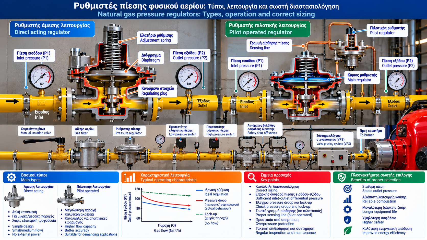
Natural Gas Pressure Regulators: Types, Operation and Correct Sizing
A natural gas pressure regulator is a critical component in installations where gas supply pressure must be reduced and maintained within suitable limits for downstream equipment.
Pressure regulators are used in industrial gas trains, boiler burners, steam generators, furnaces, process heating systems and pressure reduction stations.
Correct selection involves more than matching nominal connection size. Engineers must evaluate inlet and outlet pressure, gas flow, performance under changing loads and overpressure protection requirements.
1. What Does a Gas Pressure Regulator Do?
A regulator reduces gas pressure from a higher inlet pressure to a specified lower outlet pressure.
It adjusts an internal valve mechanism to maintain downstream pressure within the intended operating range as gas demand changes.
The main parameters are:
P1: Inlet pressure.
P2: Outlet pressure.
Q: Natural gas flow rate.
Setpoint: Nominal outlet pressure setting.
Operating range: Permissible operating conditions.
A regulator does not generate pressure. It uses the available pressure differential to control gas flow.
2. How Does a Mechanical Regulator Work?
A typical direct-acting regulator includes:
A body with gas inlet and outlet.
A valve seat and movable regulating element.
A diaphragm or other pressure-sensing element.
An adjustment spring.
A mechanical linkage.
When downstream pressure decreases as demand rises, the mechanism tends to increase valve opening.
When downstream pressure increases, the mechanism reduces valve opening.
Exact force balance and failure behavior depend on regulator design.
3. Direct-Acting Regulators
In a direct-acting regulator, downstream pressure acts on a diaphragm against a spring force to control the valve.
Advantages
Relatively simple construction.
Fewer components.
No external electrical supply required.
Suitable for many small and medium applications.
Limitations
Outlet pressure may vary with flow.
Capacity depends on size and design.
Some demanding applications require tighter control accuracy.
Suitability must be confirmed using manufacturer performance data.
4. Pilot-Operated Regulators
Pilot-operated regulators use an auxiliary regulator, known as a pilot, to control the main regulating mechanism.
The pilot senses downstream pressure and influences the pressure acting on the main regulator.
Advantages
Potentially higher flow capacity.
Often improved control accuracy.
Good response to changing loads when correctly selected.
Limitations
More complex design.
Additional inspection points.
Potential sensitivity to contamination or unsuitable sensing lines.
The choice between direct-acting and pilot-operated designs should reflect the application’s requirements.
5. What Is Pressure Droop?
Pressure droop is the reduction in regulated outlet pressure as gas flow increases.
For example, a regulator might deliver:
100 mbar at low flow.
95 mbar at medium flow.
88 mbar near high flow.
These values are hypothetical.
Droop is not necessarily a fault. It is an operating characteristic that must be evaluated using the manufacturer’s performance curves.
If outlet pressure falls below the burner’s minimum requirement, regulator selection or supply conditions must be reassessed.
6. What Is Lock-Up Pressure?
Lock-up pressure is the downstream pressure established when gas demand falls to zero and the regulator closes.
It may be higher than the regulated pressure under flowing conditions.
For example:
Operating setpoint: 100 mbar.
Pressure after demand stops: 108 mbar.
These are illustrative values.
Acceptable lock-up pressure depends on regulator characteristics and downstream equipment pressure limits.
Lock-up must not be confused with uncontrolled pressure rise due to regulator failure.
7. What Is Minimum Differential Pressure?
A regulator requires sufficient available pressure differential to operate.
The basic relationship is:
ΔP = P1 − P2
However, the required differential depends on regulator type, gas flow and operating characteristics.
If inlet pressure becomes too low, the regulator may no longer maintain the required outlet pressure.
Selection should therefore consider the minimum expected inlet pressure under load, rather than nominal supply pressure alone.
8. How Do You Select the Correct Regulator?
The selection process includes:
Step 1 — Determine gas flow
Establish maximum required gas flow and expected operating range.
Step 2 — Establish inlet pressure
Identify minimum and maximum available inlet pressures.
Step 3 — Define outlet pressure
Specify required outlet pressure and permissible deviations.
Step 4 — Review performance curves
Check flow capacity and droop characteristics of the proposed regulator.
Step 5 — Assess safety requirements
Confirm overpressure protection, isolation and compatibility with the gas train.
Step 6 — Verify installation requirements
Review orientation, straight pipe requirements, sensing lines and environmental conditions according to the manufacturer.
9. Calculating Gas Flow from Burner Input
An initial gas flow estimate can be made from burner thermal input:
Qgas = Pin / LHV
Where:
Qgas: Gas flow in Nm³/h.
Pin: Burner thermal input in kW.
LHV: Lower heating value in kWh/Nm³.
Example
For a burner with 1,500 kW thermal input and a hypothetical LHV of 10 kWh/Nm³:
Qgas = 1,500 / 10 = 150 Nm³/h
This is an initial estimate.
Final selection requires actual gas properties and consistent reference conditions.
10. Why Is Gas Flow Alone Insufficient for Sizing?
Regulator flow capacity depends on:
Inlet pressure.
Outlet pressure.
Pressure differential.
Gas density and composition.
Temperature.
Valve geometry and characteristics.
Required control accuracy.
A regulator that meets the required flow at high inlet pressure may not meet it when inlet pressure decreases.
Final selection should use certified manufacturer charts or sizing software.
11. What Is Hunting?
Hunting is a repeated oscillation of outlet pressure around the target value.
Possible causes include:
Unsuitable selection or oversizing.
Unfavorable system dynamics.
Incorrect sensing line arrangement.
Rapid changes in gas demand.
Interaction with other regulators.
Mechanical problems.
Diagnosis requires pressure measurements and evaluation of actual system behavior.
Arbitrary spring adjustments are not a safe troubleshooting method.
12. Regulators and Overpressure Protection
A pressure regulator should not automatically be considered a complete safeguard against all possible failure scenarios.
Depending on the design, additional protection may include:
Safety Shut-Off Valve (SSV): Automatic isolation following specified limit violations.
Monitor Regulator: Backup pressure-monitoring regulator.
Relief Valve: Pressure relief where permitted and required.
High Pressure Switch: Device initiating a protective action.
Selection depends on credible maximum pressure, downstream component ratings and the required safety architecture.
These devices are not interchangeable without engineering assessment.
13. What Happens When Inlet Pressure Falls?
As gas demand increases, supply pressure may decrease because of network pressure losses.
If available inlet pressure becomes insufficient, regulated outlet pressure may fall.
Possible consequences include:
Insufficient gas flow to the burner.
Inability to reach maximum burner capacity.
Low-pressure switch activation.
Unstable combustion.
Before assuming the regulator is faulty, inlet pressure and pressure losses should be evaluated under actual load.
14. Common Regulator Problems
Symptom | Possible Cause | Technical Assessment |
Low outlet pressure | Insufficient inlet pressure or flow restriction | Measure P1/P2 under load |
Pressure drop at high firing rate | Droop or insufficient capacity | Review performance curves |
Excessive pressure at no flow | Lock-up or seat tightness problem | Qualified technician inspection |
Pressure oscillation | Hunting | Record dynamic pressure |
Slow response | Mechanical or operational issue | Manufacturer-based inspection |
Protective shutdown | Limit exceeded or abnormal operating condition | Investigate event |
These are possible causes, not definitive diagnoses.
15. Where Should Pressure Be Measured?
Two measurement locations are particularly useful:
P1 — Inlet pressure: At a suitable designated point upstream of the regulator.
P2 — Outlet pressure: At a suitable designated point downstream of the regulator.
Measurements at different loads help distinguish supply limitations from regulator behavior.
Testing must be performed by authorized personnel using suitable instruments and procedures.
16. Regulator Maintenance
Maintenance should follow manufacturer instructions and the installation risk assessment.
It may include:
External inspection.
Required leakage checks.
Outlet pressure evaluation.
Load-response assessment.
Lock-up testing where specified.
Filter inspection.
Sensing line inspection.
Verification of related protective devices.
Disassembly, spring replacement and internal adjustments are specialist activities.
17. Relevant Technical Standards
Depending on the application, relevant standards include:
EN 88-1: Pressure regulators and associated safety devices for gas appliances.
EN 334: Gas pressure regulators for inlet pressures up to 100 bar.
EN 14382: Gas safety shut-off devices for pressure regulating stations and installations.
EN 676: Automatic forced draught burners for gaseous fuels.
EN 15001-1: Design and construction of gas installations within its scope.
Applicability depends on regulator type, operating pressure and installation requirements.
Conclusion
A natural gas pressure regulator is essential for stable and safe fuel supply to burners and industrial gas systems.
Correct selection requires knowledge of minimum and maximum inlet pressure, required outlet pressure and actual gas flow.
Pressure droop, lock-up and hunting must be considered during sizing and troubleshooting.
Final selection, installation, adjustment and testing must be performed by qualified personnel using manufacturer data and applicable safety requirements.