
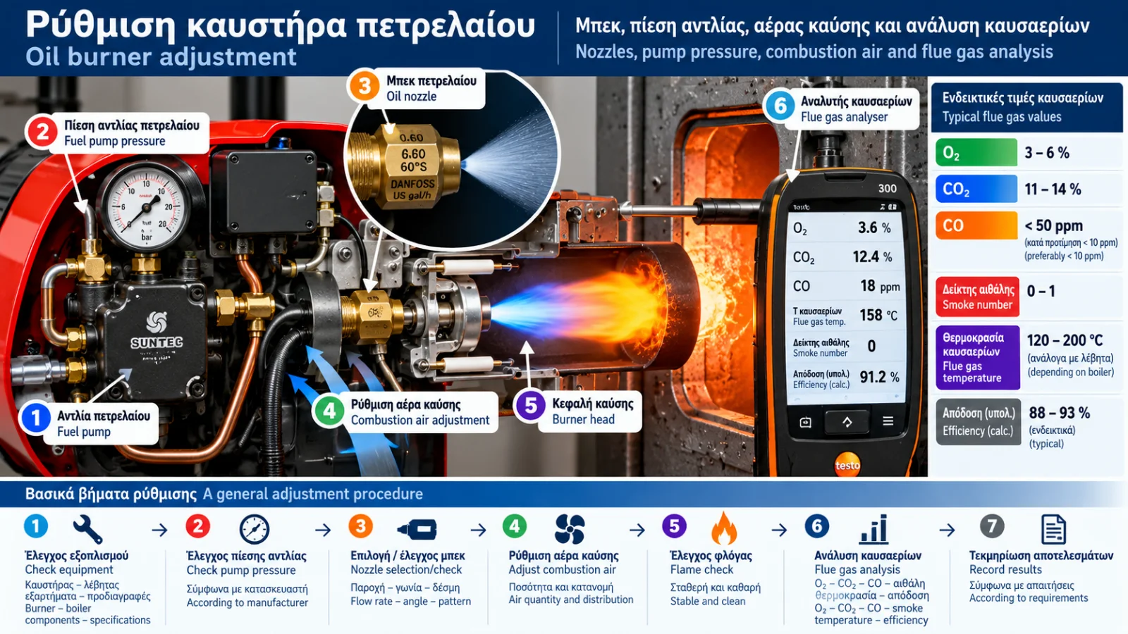
Oil Burner Adjustment: Nozzles, Pump Pressure and Flue Gas Analysis
Correct oil burner adjustment is essential for the safe, reliable and efficient operation of an oil-fired heating installation.
It is not enough for a burner to ignite and produce heat. Fuel must be properly atomised, mixed with an appropriate quantity of combustion air and burned with a stable flame, without excessive soot or hazardous carbon monoxide emissions.
Burner adjustment involves several interconnected parameters: nozzle selection, fuel pump pressure, combustion airflow, burner head configuration and flue gas assessment.
Changing one parameter can affect the overall combustion process.
This Thermosphere.gr technical guide explains the fundamental principles, measurement methods and common mistakes associated with oil burner adjustment.
Important: This article explains technical concepts and is not a commissioning procedure for unqualified users. Actual fuel-system and combustion adjustments require a qualified technician, appropriate instruments and the manufacturer's instructions.
1. What Does Correct Oil Burner Adjustment Mean?
Correct adjustment means operating the burner within its manufacturer's specified limits while ensuring proper compatibility with the boiler.
The main objectives are:
Appropriate boiler heat input.
Reliable ignition and stable flame.
Sufficient combustion air.
Minimal soot formation.
Acceptable CO emissions under applicable requirements.
Suitable flue gas temperatures.
Reliable operation of safety controls.
Correct adjustment cannot be determined from a single pressure value or CO₂ reading.
The complete operating condition must be assessed.
2. Understanding Oil Burner Nozzle Specifications
Oil burner nozzles are typically identified by three principal characteristics:
Nominal flow rate, usually expressed in US gallons per hour (GPH).
Spray angle, expressed in degrees.
Spray pattern, according to the manufacturer's designation.
For example, a marking of 0.60 GPH – 60° indicates nominal flow and spray angle under specified reference conditions.
It does not mean that the nozzle delivers exactly that quantity of fuel at every operating pressure.
Actual flow depends on differential pressure, fuel density, viscosity and nozzle characteristics.
Spray-pattern classifications should not automatically be considered interchangeable between manufacturers.
3. How Does Pump Pressure Affect Nozzle Flow?
For a pressure-atomising nozzle, fuel flow generally increases as differential pressure increases.
For the same nozzle and approximately constant fuel properties, the following relationship applies:
Q₂ = Q₁ × √(Δp₂ / Δp₁)
Where:
Q₁ is the initial flow rate.
Q₂ is the estimated new flow rate.
Δp₁ is the initial differential pressure across the nozzle.
Δp₂ is the new differential pressure.
This is an approximate engineering relationship used to understand the effect of pressure, not a standalone adjustment instruction.
Illustrative Calculation
Assume a nozzle has a nominal flow rate of 0.60 US GPH at a reference pressure of 7 bar.
If the differential pressure were hypothetically increased to 10 bar:
Q₂ = 0.60 × √(10 / 7)
Q₂ ≈ 0.717 US GPH
The estimated flow increases by approximately 19.5%.
This is not a recommended setting. Permitted pressure and nozzle selection depend on the burner manufacturer's specifications.
4. Calculating Fuel Heat Input
Burner heat input is related to fuel mass flow and the fuel's lower heating value.
The fundamental relationship is:
Heat input = Fuel mass flow × Lower heating value
In engineering notation:
Pinput = ṁ × Hi
Where:
Pinput is fuel heat input in kW.
ṁ is fuel mass flow in kg/h.
Hi is lower heating value in kWh/kg.
For example, assuming a hypothetical fuel consumption of 2.5 kg/h and a lower heating value of 11.8 kWh/kg:
Pinput = 2.5 × 11.8 = 29.5 kW
This is the fuel heat input, not the useful heating output delivered to the water.
Useful output depends on boiler efficiency under the relevant operating conditions.
Actual fuel properties should be used for practical calculations.
5. Why Does Nozzle Spray Angle Matter?
The spray angle influences the geometry of the fuel spray inside the combustion chamber.
Different spray angles create different droplet distributions and interactions with combustion airflow.
Correct selection depends on:
Burner head design.
Combustion chamber geometry.
Required flame characteristics.
Burner specifications.
Boiler and burner compatibility.
Replacing a nozzle with a different spray angle or pattern without verifying suitability may cause poor mixing, flame instability or unsuitable heat distribution.
Only manufacturer-approved configurations should be used.
6. What Is Combustion Air?
Oil combustion requires oxygen.
In forced-draught oil burners, a fan supplies air to the burner head, where it interacts with the atomised fuel.
Air quantity and distribution influence combustion quality.
Insufficient air may cause incomplete combustion, soot formation and increased CO emissions.
Excessive air may increase flue gas heat losses and affect flame stability.
The objective is not simply to minimise airflow but to provide sufficient, appropriately distributed air for safe and stable combustion.
7. Understanding Excess Air
The theoretical quantity of air needed for complete combustion is called the stoichiometric air requirement.
In practice, burners usually operate with some excess air to support adequate mixing and complete combustion.
The excess-air ratio is often represented by λ.
λ = 1: theoretically stoichiometric conditions.
λ greater than 1: excess air.
λ less than 1: less air than the stoichiometric requirement.
Practical estimates of λ from flue gas measurements depend on assumptions about the fuel and combustion process.
The appropriate operating range depends on the burner and manufacturer requirements.
8. What Does a Flue Gas Analyser Measure?
A flue gas analyser is an essential tool for assessing combustion performance.
Depending on the instrument and installed sensors, it may display:
Parameter | Meaning |
|---|---|
O₂ | Residual oxygen in flue gases |
CO₂ | Measured or calculated carbon dioxide |
CO | Carbon monoxide concentration |
Flue gas temperature | Temperature at the sampling point |
Combustion air temperature | Reference air temperature |
λ | Estimated excess-air ratio |
Flue gas losses | Calculated heat-loss estimate |
Combustion efficiency | Calculated performance indicator |
Not all instruments provide the same measurements.
Correct sampling technique, calibration and sensor condition are important for reliable results.
9. What Does O₂ Tell Us?
Oxygen concentration indicates how much oxygen remains in the combustion products.
Higher O₂ may indicate greater excess air, although air leakage into the flue system can also affect the reading.
A lower O₂ value is not automatically better.
If low oxygen coincides with increased CO or soot, combustion may be deteriorating.
O₂ must therefore be interpreted alongside other measurements.
10. What Does CO₂ Tell Us?
Carbon dioxide is a product of fuel combustion.
A flue gas analyser may measure CO₂ directly or calculate it using O₂ and the selected fuel type.
Under otherwise comparable conditions, higher CO₂ often corresponds to lower excess air.
However, maximising CO₂ is not necessarily the correct adjustment objective.
CO, soot, flame stability and manufacturer specifications must also be considered.
11. Why Is Carbon Monoxide Important?
Carbon monoxide is a toxic gas that may be produced during incomplete combustion.
Elevated CO readings can be associated with:
Insufficient or poorly distributed combustion air.
Poor fuel atomisation.
Unsuitable flame geometry.
Combustion chamber problems.
Abnormal flue conditions.
CO is commonly displayed in parts per million (ppm).
A distinction must be made between the directly measured concentration and values corrected to air-free conditions or a specified oxygen reference.
An elevated CO reading must not be ignored simply because the burner continues operating.
Assessment and corrective action require a qualified technician.
12. What Is a Smoke or Soot Test?
Soot is associated with incomplete combustion and the formation of carbon particles.
Oil burner combustion assessment may include a smoke test using a recognised method, such as the Bacharach smoke number.
The measurement requires appropriate equipment and technique.
Soot formation may be associated with:
Insufficient combustion air.
Poor atomisation.
Incorrect nozzle selection.
Burner head problems.
Contaminated boiler surfaces.
Unstable combustion.
Soot deposits on heat-exchange surfaces can reduce heat transfer and increase operating losses.
Smoke testing is therefore an important part of oil burner combustion assessment.
13. Why Is Flue Gas Temperature Measured?
Flue gas temperature is influenced by burner operation, boiler condition and installation characteristics.
Elevated temperatures may be associated with:
Fouled heat-exchange surfaces.
Unsuitable firing rate.
Increased flue gas losses.
Different boiler operating conditions.
Very low flue gas temperatures are not always desirable.
In conventional non-condensing boilers and unsuitable chimney systems, low temperatures can increase the risk of condensation and corrosion.
Acceptable operating temperatures depend on boiler and flue-system design.
14. Understanding Flue Gas Losses
Some of the fuel's energy leaves the system with the hot combustion products.
Flue gas analysers can estimate these losses using the temperature difference between flue gases and combustion air, gas composition and fuel-related parameters.
Such calculations are useful for assessing combustion performance.
However, the efficiency figure displayed by a portable analyser is not necessarily equal to the heating system's overall seasonal efficiency.
It may exclude boiler standby losses, other thermal losses and auxiliary electricity consumption.
15. Professional Combustion Assessment
A professional assessment is not based on a single measurement.
At a general level, it involves:
Identifying the burner and boiler models.
Reviewing official technical specifications.
Checking nozzle suitability and permitted heat input.
Assessing fuel supply and relevant components.
Verifying required safety functions.
Performing combustion measurements under specified conditions.
Evaluating O₂, CO₂, CO, soot and temperatures.
Documenting findings and corrective work.
The actual work sequence must follow equipment instructions and safety requirements.
16. Common Oil Burner Adjustment Mistakes
Adjusting by Flame Appearance Alone
Flame appearance cannot accurately reveal CO emissions, excess air or flue gas losses.
Arbitrarily Increasing Pump Pressure
Higher pressure changes fuel flow and may cause unsuitable boiler heat input.
Selecting a Nozzle Only by GPH
Spray angle and spray pattern also matter.
Trying to Achieve the Highest Possible CO₂
Good combustion is not defined by CO₂ alone. CO, soot and flame stability must also be assessed.
Ignoring Boiler Condition
A fouled boiler may have increased heat losses even when the burner has been inspected.
Comparing Measurements Taken Under Different Conditions
Comparisons should account for operating temperature, sampling location, fuel type and calculation method.
17. Frequently Asked Questions
What Pump Pressure Should an Oil Burner Use?
There is no universal value. Required pressure depends on the burner model, nozzle and manufacturer specifications.
Can I Install a Larger Nozzle to Increase Heating Output?
Not without professional evaluation. Higher fuel flow may overload the boiler and create combustion problems.
What Is the Correct CO₂ Reading for an Oil Burner?
The appropriate range depends on the burner, boiler and fuel. A universal target should not be applied to every installation.
Why Does an Oil Burner Produce Soot?
Possible causes include insufficient combustion air, atomisation problems and other incomplete-combustion conditions.
Does High Flue Gas Temperature Always Mean Incorrect Adjustment?
No. Boiler design, condition and actual operating conditions must be considered.
Can a Burner Operate with Poor Combustion?
Yes. Successful ignition does not establish safe or efficient combustion.
Is a Flue Gas Analyser Necessary?
Reliable combustion assessment requires appropriate measurements. A flue gas analyser is an essential tool alongside other specified tests.
Conclusion
Correct oil burner adjustment involves coordinated selection of components, fuel-flow control, combustion-air management and documented flue gas analysis.
The nozzle and pump pressure influence fuel delivery, while airflow and burner head design significantly affect mixing and flame stability.
Measurements of O₂, CO₂, CO, soot and flue gas temperature help assess actual combustion performance.
Oil burners should not be adjusted using universal values or visual observation alone. Correct adjustment requires manufacturer specifications, suitable instruments and a qualified technician.
Technical References and Further Reading
EN 267: Automatic forced draught burners for liquid fuels.
EN 50379: Specifications for portable electrical apparatus designed to measure combustion flue gas parameters of heating appliances.
EN 230: Automatic burner control systems for oil burners.
Danfoss: Oil pump and nozzle technical documentation — https://www.danfoss.com/
Riello: Official burner manuals and adjustment data — https://www.riello.com/
Baltur: Oil burner technical documentation — https://www.baltur.com/
Testo: Technical information on combustion analysis — https://www.testo.com/
These references provide technical background. Actual settings must be obtained from the manual for the exact burner model and measurements from the installation.
Safety note: Fuel, airflow and combustion adjustments must not be performed by unqualified users. Incorrect adjustment may cause soot formation, hazardous CO emissions, equipment damage or fire risks.
Thermosphere.gr — Technical knowledge for heating and building systems.