
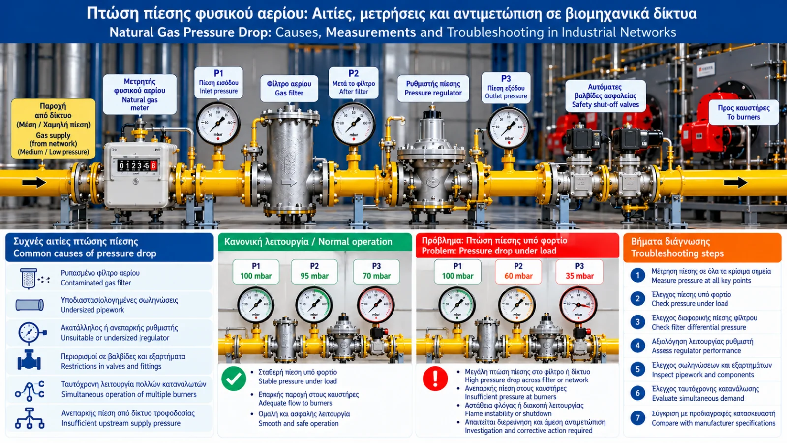
Natural Gas Pressure Drop: Causes, Measurements and Troubleshooting in Industrial Networks
Natural gas pressure drop is one of the most important supply-related issues affecting industrial burners, boilers, steam generators and process heating installations.
A system may operate normally at low firing rates but experience unstable operation, reduced burner capacity or low-gas-pressure safety trips when demand increases.
The key diagnostic question is not simply whether pressure is low, but where the pressure loss occurs and under which operating conditions.
1. What Is Natural Gas Pressure Drop?
As gas flows through piping and equipment, friction and local resistance cause pressure losses.
For two measurement points:
ΔP = P1 − P2
where P1 and P2 are the measured pressures at the two locations.
For detailed engineering calculations, flow conditions, elevation differences and gas compressibility may also need consideration.
A pressure drop does not automatically indicate a fault. All properly designed gas networks have expected pressure losses.
A problem exists when the remaining pressure at the consumer is insufficient for its required operating conditions.
2. Why Does Pressure Drop Increase with Flow?
When burner demand increases, more gas must pass through the network.
Higher flow generally increases frictional and local pressure losses.
The precise relationship depends on gas properties, flow regime and component characteristics.
A system may therefore show adequate pressure with the burner off but insufficient pressure at maximum load.
3. Static Pressure Versus Pressure Under Load
Static pressure is measured when little or no gas is flowing.
Flowing pressure is measured while equipment is consuming gas.
Illustrative readings might be:
No-flow pressure: 100 mbar.
Low-load pressure: 92 mbar.
High-load pressure: 65 mbar.
These are hypothetical values. Their acceptability depends on equipment requirements and installation design.
A substantial load-related change should prompt an assessment of supply capacity.
4. Common Causes of Pressure Drop
Insufficient upstream supply pressure
The available supply pressure may fall below the required level during high demand.
Undersized piping
Small internal diameter, long pipe runs and numerous fittings can increase pressure losses.
Contaminated gas filter
Accumulated particles may increase resistance across a gas filter.
Unsuitable or undersized regulator
A regulator may not maintain the required outlet pressure at the available inlet pressure and demand.
Restrictions in valves and fittings
A restrictive component or improperly positioned isolation valve can create additional resistance.
Simultaneous operation of multiple consumers
Combined demand may exceed the actual capacity of the supply system.
5. How Does a Contaminated Gas Filter Affect Pressure?
Gas filters protect downstream equipment by retaining particles.
As contamination increases, flow resistance may rise.
The pressure difference across the filter is:
ΔPfilter = Pupstream − Pdownstream
For example, if readings under known flow are 180 mbar before the filter and 165 mbar after it:
ΔPfilter = 15 mbar
Whether this is acceptable must be determined from the filter manufacturer's performance data at the measured flow.
There is no universal allowable pressure drop for all gas filters.
6. How Does the Regulator Affect Outlet Pressure?
A pressure regulator maintains outlet pressure within its specified performance range despite changes in inlet pressure and demand.
If inlet pressure becomes insufficient or flow demand exceeds the regulator's capacity, outlet pressure may fall outside the required range.
Normal pressure droop must be distinguished from an actual malfunction.
Manufacturer flow curves and regulator specifications are essential for proper assessment.
7. Where Should Pressure Be Measured?
Useful diagnostic locations may include:
Installation inlet.
Upstream and downstream of the gas filter.
Upstream and downstream of the pressure regulator.
Gas train inlet.
The designated burner gas-pressure test point.
Exact locations depend on the installation design and approved measurement connections.
Measurements must be performed by qualified personnel using suitable equipment and safe procedures.
8. Why Are Simultaneous Measurements Important?
A single pressure reading may not reveal the root cause.
If both regulator inlet and outlet pressures fall together, the cause may lie upstream.
If inlet pressure remains adequate but outlet pressure falls excessively, regulator capacity and downstream operating conditions should be investigated.
Simultaneous pressure and burner-load records provide stronger diagnostic evidence.
9. Pressure Drop Across the Gas Train
A gas train may contain filters, regulators, pressure switches, safety shut-off valves and other components.
Each has its own flow characteristics.
Automatic safety shut-off valves, for example, have pressure losses that depend on flow and specific product design.
Gas trains with identical nominal connection sizes do not necessarily have identical flow capacity.
10. What Happens When Burner Gas Pressure Becomes Too Low?
If pressure falls below a defined limit, the low-gas-pressure switch or another protective function may activate.
Depending on the burner control system, this may cause:
Start inhibition.
Controlled shutdown.
Protective lockout.
Inability to operate at high firing rate.
The exact response depends on the burner manufacturer and combustion management system.
Repeatedly resetting a burner without investigating the cause is not an appropriate corrective action.
11. Pressure Drop Troubleshooting Table
Observation | Possible Cause | Assessment |
|---|---|---|
Low pressure at installation inlet | Upstream supply limitation | Check available inlet pressure |
High differential pressure across filter | Increased filter resistance | Compare with manufacturer data |
Adequate regulator inlet, low outlet | Capacity limitation or malfunction | Review regulator performance |
Normal pressure at low load, low at high load | Insufficient supply capacity | Test under design demand |
Pressure falls when another burner starts | Increased combined demand | Assess common supply line |
Frequent low-pressure switch trips | Actual low pressure or instrument issue | Review pressure trends and events |
These are diagnostic possibilities, not definitive fault identifications.
12. Example: Industrial Installation with Two Burners
Consider a hypothetical installation with two burners.
Burner A requires 100 Nm³/h and Burner B requires 80 Nm³/h at maximum load.
With only Burner A operating, supply pressure may remain satisfactory.
When Burner B starts, total demand may reach 180 Nm³/h.
If pressure drops significantly only under combined operation, the common supply line, regulator and associated equipment should be assessed.
This observation alone does not prove that larger piping is required.
13. How SCADA Supports Diagnosis
Where suitable instrumentation is available, SCADA may record:
Inlet pressure.
Regulator outlet pressure.
Natural gas flow.
Burner operating status.
Burner load.
Protective trips.
Comparing these trends helps identify correlations.
For example, a repeatable pressure drop whenever a second burner starts may direct attention toward the shared supply system.
14. Why Not Simply Increase the Pressure Setting?
Increasing the regulator outlet pressure without diagnosing the cause is not an appropriate response to inadequate gas flow.
It may expose downstream equipment to unacceptable pressure or interfere with protective settings.
The root cause and design limits must be established first.
Any pressure-setting changes must be performed by qualified personnel under approved procedures.
15. When Is Network Re-Sizing Required?
Reassessment may be needed when:
New burners are added.
Installed thermal capacity increases.
Supply conditions change.
Pipework is modified.
Repeated pressure drops occur at maximum load.
Combined demand exceeds original design assumptions.
The engineering assessment should cover the complete route from the supply point to the most demanding consumer.
16. Preventing Pressure Problems
Reliable operation depends on:
Proper initial network sizing.
Correct selection of regulators and filters.
Planned inspection and maintenance.
Suitable pressure monitoring.
Recording pressure behavior under load.
Evaluating the effect of new consumers.
Following manufacturer specifications and applicable regulations.
17. Relevant Technical Standards
Depending on the installation, relevant standards may include:
EN 15001-1: Design and construction requirements for gas installations within its scope.
EN 1775: Gas pipework for buildings.
EN 334: Gas pressure regulators.
EN 676: Forced draught burners for gaseous fuels.
EN 14382: Gas safety shut-off devices.
The applicability of each standard depends on the installation's technical characteristics and regulatory framework.
Conclusion
Natural gas pressure drop is not always evidence of a fault. It is an expected characteristic of gas flowing through piping and components.
The critical problem arises when pressure losses exceed design expectations or when the pressure available at the burner becomes insufficient.
Effective diagnosis relies on measurements at multiple locations, records of actual flow demand and comparison with equipment specifications.
Investigation, maintenance and modifications of natural gas installations must be performed by authorized professionals.