
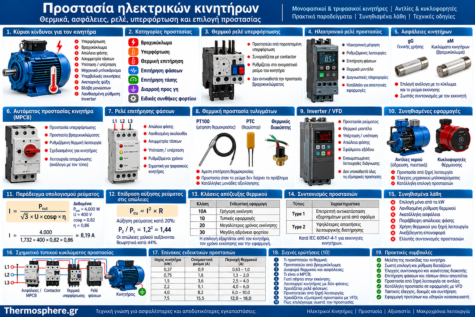
Electric Motor Protection: Complete Guide to Overload Relays, Fuses, Circuit Breakers and Motor Safety
Protecting an electric motor involves much more than installing a fuse or circuit breaker in an electrical panel.
An electric motor can suffer serious damage from prolonged overload, phase failure, overheating, mechanical blockage, abnormal supply voltage, or incorrect starter settings—even when no short circuit occurs.
Effective motor protection therefore requires a coordinated combination of protective devices, correct selection based on the motor’s characteristics, and an understanding of the actual operating load.
This is particularly important in water supply and heating installations. A water pump may draw excessive current because of mechanical obstruction, a three-phase motor may overheat following the loss of one supply phase, and a heating circulator may experience abnormal temperatures under unfavorable operating conditions.
This guide explains the main electrical and thermal protection methods, their differences, selection principles, common mistakes, and practical applications.
Important: This article is intended for technical education. Protective devices must be selected, installed, configured, and tested by appropriately qualified professionals in accordance with applicable regulations, standards, and manufacturer instructions.
1. Why Do Electric Motors Need Protection?
An electric motor converts electrical energy into mechanical energy.
During operation, energy losses generate heat in the windings, magnetic core, and mechanical components.
Under normal conditions, the motor’s temperature remains within the manufacturer’s specified limits.
However, abnormal operating conditions can significantly increase electrical and thermal stress.
Main risks
Prolonged overload.
Short circuits.
Phase loss.
Voltage imbalance.
Undervoltage or overvoltage.
Mechanical blockage.
Excessively frequent starts.
Insufficient cooling.
Insulation failure.
Incorrect variable frequency drive (VFD) configuration.
A properly designed protection system detects dangerous conditions and limits their consequences.
No single protective device automatically covers every possible motor fault.
2. Main Categories of Electric Motor Protection
Motor protection systems can be classified according to the condition they monitor.
Protection category | Main purpose |
Short-circuit protection | Limit the consequences of very high fault currents |
Overload protection | Prevent excessive thermal stress |
Winding temperature protection | Monitor actual or estimated motor temperature |
Phase monitoring | Detect phase loss, incorrect phase sequence, or imbalance |
Voltage monitoring | Detect unacceptable supply voltage variations |
Earth fault protection | Detect applicable faults to earth |
Application-specific protection | Detect dry running, mechanical blockage, or abnormal load conditions |
A reliable system combines the required functions rather than assuming that one device can replace all others.
3. What Is Electric Motor Overload?
Motor overload occurs when operating conditions produce thermal stress beyond the motor’s allowable limits.
It is frequently associated with excessive current, although motor temperature is also influenced by cooling, ambient conditions, and operating duty.
Common causes
Excessive mechanical load.
Locked or obstructed shaft.
Worn bearings.
Poor ventilation.
Voltage imbalance.
Prolonged starting time.
Excessive starting frequency.
Why is overload dangerous?
Copper losses in the motor windings can be approximated by:
Pcu = I² × R
Where:
Pcu = copper losses.
I = winding current.
R = winding resistance.
This equation shows that copper losses increase with the square of the current.
Example
If current increases by 20%, assuming constant winding resistance:
P₂ / P₁ = 1.2² = 1.44
Copper losses theoretically increase by 44%.
This does not mean the motor temperature increases by 44%. It demonstrates why even a moderate current increase can cause substantial additional heating.
4. What Is a Thermal Overload Relay?
A thermal overload relay is a protective device designed to respond to sustained motor overload conditions.
It is commonly used together with an electromagnetic contactor.
Operating principle
Traditional thermal overload relays use heat-sensitive elements, often bimetallic strips, that respond to heating caused by current.
When the thermal stress exceeds the relay’s designed operating threshold, the relay activates its trip mechanism or control circuit.
What does it protect against?
Primarily sustained overload conditions that may cause excessive motor heating.
What does it not replace?
A conventional thermal overload relay does not independently provide the required short-circuit protection.
It must therefore be coordinated with an appropriate short-circuit protective device.
5. How to Select and Set a Thermal Overload Relay
Selection begins with the motor nameplate.
Motor power in kilowatts alone is insufficient to determine the correct overload setting.
Required information
Rated motor current.
Rated voltage.
Motor connection arrangement.
Operating duty.
Starting conditions.
Position of the overload relay in the circuit.
Manufacturer instructions.
Example
Consider a motor with a nameplate rated current of:
In = 8.2 A
If the overload relay measures line current during normal operation and its manufacturer specifies a setting based on motor rated current, an initial evaluation would be made around 8.2 A.
The final setting must still be verified against the relay instructions, actual circuit arrangement, and operating conditions.
Important: In certain star–delta starter arrangements, the relay’s position affects the current passing through it. The same setting must not be applied indiscriminately to every configuration.
6. What Does Thermal Overload Trip Class Mean?
Overload protection devices are available with different trip classes.
A trip class describes the device’s operating-time characteristics under defined test conditions.
Common classes
Examples include:
Class 10A.
Class 10.
Class 20.
Class 30.
These classes do not simply indicate better or worse protection.
They describe different time-current responses, including behavior under specified overload conditions.
Why does trip class matter?
A motor that accelerates quickly has different requirements from a motor driving a high-inertia load.
An unsuitable trip class may result in:
Unwanted trips during normal starting.
Inadequate protection against overheating.
Incorrect coordination with the motor’s thermal capabilities.
The selection must account for starting time, motor thermal withstand characteristics, and the protection device’s operating curve.
7. Thermal vs Electronic Overload Relays
In addition to conventional bimetallic relays, electronic overload relays are widely used.
Electronic devices measure electrical quantities and apply protection algorithms.
Feature | Thermal overload relay | Electronic overload relay |
Operating principle | Thermal response of sensing elements | Electronic measurement and processing |
Adjustments | Usually basic | Often more extensive |
Additional protection | Depends on model | May include phase monitoring and thermal models |
Diagnostic information | Usually limited | May provide detailed fault information |
Complexity | Generally lower | Depends on device |
Advantages of electronic protection
Depending on the model, electronic overload relays can provide more flexible protection settings and additional diagnostic information.
However, available functions differ significantly between manufacturers and products.
8. Electric Motor Fuses
Fuses protect electrical circuits against overcurrents within their specified operating characteristics.
Motor circuits require special consideration because starting current can be significantly higher than normal operating current.
Why is fuse selection important?
An incorrectly selected fuse may:
Operate unnecessarily during motor starting.
Fail to provide the required coordination with other equipment.
Provide inadequate protection for the intended application.
Common fuse utilization categories
gG fuses
General-purpose fuses providing overcurrent protection within their specified operating range.
aM fuses
Partial-range fuses designed for short-circuit protection in motor circuits.
They require complementary overload protection.
Key principle
Fuse selection must consider circuit characteristics, expected fault current, starting behavior, and coordination with the motor starter.
A fuse should not be selected solely from the motor’s power rating.
9. Miniature Circuit Breakers vs Motor Protection Circuit Breakers
A conventional miniature circuit breaker and a dedicated motor protection circuit breaker are not necessarily interchangeable.
Miniature Circuit Breaker (MCB)
An MCB provides circuit protection according to its applicable standard and rated characteristics.
Important parameters include:
Rated current.
Tripping characteristic.
Breaking capacity.
Circuit installation conditions.
Motor Protection Circuit Breaker (MPCB)
An MPCB is designed for motor circuit applications.
Depending on its design and certification, it may provide:
Motor overload protection.
Short-circuit protection.
Adjustable thermal protection.
Isolation functionality, where specifically rated.
Additional motor protection features.
Comparison
Feature | MCB | MPCB |
Typical application | General circuit protection | Motor circuit protection |
Thermal adjustment | Usually fixed | Often adjustable |
Motor starting characteristics | Require evaluation | Designed for appropriate motor applications |
Short-circuit protection | According to device ratings | According to device ratings |
Motor overload protection | Not automatically assured | Depends on certified functionality |
Even when a device is marketed as a motor protection circuit breaker, its breaking capacity and coordination requirements must be verified.
10. Short Circuits and Breaking Capacity
A short circuit is an electrical fault that may produce extremely high current.
The protective device must be suitable for the prospective short-circuit current at its installation point.
What is breaking capacity?
Breaking capacity describes the ability of a protective device to interrupt a specified fault current under defined conditions.
Selection must consider:
Operating voltage.
Prospective short-circuit current.
Applicable product standard.
Other equipment in the circuit.
Certified combinations of protective devices, where applicable.
Example
Suppose an electrical study identifies a prospective short-circuit current of 6 kA at a particular distribution panel.
A protective device cannot be selected only by its rated operating current.
Its suitability for the prospective fault current, operating voltage, and installation arrangement must also be confirmed.
This example alone is not sufficient to determine the final device specification.
11. What Is Motor Protection Coordination?
Protection coordination describes how protective and switching devices operate together.
A typical motor starter may include:
A short-circuit protective device.
A contactor.
An overload relay.
Additional monitoring relays.
Why is coordination important?
During a fault, the combined equipment must behave according to its intended coordination characteristics.
Type 1 and Type 2 Coordination
Under IEC 60947-4-1, appropriate motor starters may be evaluated according to specified coordination types.
Type 1 Coordination
Following a short circuit, repair or replacement of components may be necessary, but the equipment must not create an unsafe condition.
Type 2 Coordination
The combination must satisfy stricter requirements concerning its condition after the fault.
Under the specified standard conditions, limited contact welding may be permissible if the contacts can be separated as required.
Practical significance
It is not enough for each component to have suitable individual ratings.
The complete combination must be appropriate and documented for the intended application.
12. Protection Against Phase Failure
Loss of one supply phase can create dangerous operating conditions in a three-phase motor.
Depending on load and operating state, the motor may:
Fail to start.
Develop insufficient torque.
Continue running with increased current in the remaining phases.
Overheat.
How is phase failure detected?
Suitable solutions may include:
Phase monitoring relays.
Electronic motor protection relays.
Integrated protection functions in compatible equipment.
Important limitation
A phase monitoring relay does not necessarily detect every possible fault occurring downstream of its measurement point.
The monitoring location and overall circuit architecture are important.
13. Voltage and Current Imbalance
In an ideal three-phase system, the supply voltages are balanced.
In practice, deviations can occur.
Even a relatively small voltage imbalance can produce a more significant current imbalance in an induction motor.
Possible causes
Supply network problems.
Poor electrical connections.
Uneven network loading.
Connection faults.
Equipment problems.
Why is imbalance dangerous?
It can increase thermal stress and reduce available motor torque.
What should be evaluated?
Line-to-line voltages.
Phase currents.
Connection condition.
Behavior under load.
Manufacturer operating limits.
Assessment requires suitable measuring instruments and professional interpretation.
14. Undervoltage and Overvoltage Protection
Supply voltage affects motor performance and thermal behavior.
Undervoltage
Reduced voltage can decrease available motor torque.
If the mechanical load remains demanding, the motor may operate under unfavorable current and heating conditions.
Overvoltage
Excessive voltage can increase electrical and magnetic stress, depending on motor design and supply frequency.
Voltage monitoring relays
Suitable devices may monitor:
Minimum voltage.
Maximum voltage.
Phase failure.
Phase sequence.
Voltage imbalance, where supported.
Thresholds and time delays must be selected according to the application.
15. Internal Motor Thermal Protection
Current measurement does not always fully represent the motor’s actual thermal condition.
Some motors therefore incorporate thermal sensors or switches within their windings.
Common technologies
PTC thermistors
Temperature-sensitive components whose resistance changes significantly near a specified temperature region.
They operate with a compatible evaluation device.
PT100 / RTD sensors
Resistance temperature detectors that allow temperature measurement through suitable monitoring equipment.
Thermal switches
Devices that change electrical state when a specified temperature threshold is reached.
Advantages
Internal thermal protection can identify dangerous overheating even when motor current is not obviously excessive.
Limitations
Thermal sensors do not automatically replace short-circuit protection or other required safety functions.
16. Locked-Rotor and Prolonged Starting Protection
A motor that cannot rotate or accelerate normally may draw high current.
Possible causes
Mechanical obstruction.
Bearing failure.
Pump impeller blockage.
Excessive starting load.
Supply problems.
Incorrect connections.
Why may ordinary overload protection be insufficient?
Some conditions require specialized or faster detection, depending on the motor’s thermal withstand capability.
Suitable systems may provide:
Locked-rotor protection.
Starting-time monitoring.
Motor thermal modeling.
Advanced electronic protection.
Application in pumps
A blocked impeller or shaft requires investigation of the underlying mechanical problem.
Repeatedly resetting a protective device without identifying the cause can worsen the damage.
17. Dry-Run Protection for Water Pumps
Dry running is a significant risk in water pumping applications.
Depending on pump design, insufficient liquid can cause:
Inadequate cooling.
Mechanical seal damage.
Component overheating.
Premature wear.
Pump failure.
How can dry running be detected?
Suitable systems may use:
Level sensors.
Flow switches.
Pressure sensors.
Electrical power monitoring.
Underload monitoring.
Dedicated pump controller functions.
Important consideration
Dry running does not always increase motor current.
In some centrifugal pumps, absorbed mechanical power may decrease when insufficient liquid is present.
Therefore, a conventional overload relay is not a universal dry-run protection solution.
18. Motor Protection with Variable Frequency Drives (VFDs)
Variable frequency drives often include built-in protection functions.
Depending on the product, these may monitor:
Motor current.
Motor thermal model.
DC-link overvoltage.
Undervoltage.
Drive overheating.
Phase loss or imbalance.
Output faults.
Overload conditions.
Drive protection vs motor protection
Protecting the VFD and protecting the connected motor are separate objectives, even when the same device performs both functions.
Installing a VFD does not automatically guarantee complete protection against every possible motor fault.
Additional considerations
Motor-drive installations must also consider:
Motor suitability for inverter supply.
Cable type and length.
Electromagnetic compatibility.
Voltage stress on winding insulation.
Cooling at reduced speed.
Appropriate earth fault and residual-current protection.
Safe isolation and stored energy in the DC link.
Equipment selection must follow manufacturer instructions and applicable standards.
19. Protection of Single-Phase Motors and Heating Circulators
Single-phase motors have different operating characteristics and protection requirements from three-phase motors.
Common risks
Capacitor failure.
Starting difficulties.
Prolonged excessive current.
Mechanical blockage.
Overheating.
Unsuitable supply conditions.
Important selection factors
Rated current.
Required thermal protection.
Capacitor specifications.
Starting frequency.
Cooling conditions.
Manufacturer instructions.
Modern electronic circulators
High-efficiency heating circulators may incorporate power electronics and diagnostic functions.
External protection must be compatible with the specific equipment.
Protection arrangements suitable for conventional induction motors should not automatically be applied to electronically controlled circulators.
20. Practical Example: Selecting Protection for a Water Pump Motor
Consider a hypothetical three-phase pump motor.
Motor data
Parameter | Value |
Mechanical output power | 4 kW |
Supply | 400 V, 50 Hz |
Efficiency | 0.86 |
Power factor | 0.82 |
Starting method | Direct-on-line, if permitted |
Application | Centrifugal water pump |
Estimated rated current
For a balanced three-phase motor:
Pout = √3 × U × I × cosφ × η
Therefore:
I = Pout / (√3 × U × cosφ × η)
Substituting the values:
I = 4,000 / (1.732 × 400 × 0.82 × 0.86)
I ≈ 8.19 A
This is a theoretical estimate based on assumed parameters.
For an actual installation, the motor nameplate current and manufacturer data must be used.
What must the protection design consider?
Overload protection appropriate for the motor’s rated current.
Short-circuit protection with sufficient breaking capacity.
A compatible contactor, where required.
Documented coordination between protective devices.
Phase monitoring, where appropriate.
Dry-run protection, where the application requires it.
Appropriate circuit and conductor protection.
Required protection against electric shock.
What cannot be determined from this example?
A specific fuse or circuit breaker rating cannot responsibly be selected from motor power and estimated current alone.
Additional information is required about the supply network, cables, prospective short-circuit current, starting characteristics, and equipment coordination.
21. Common Electric Motor Protection Mistakes
Mistake | Possible consequence |
Selecting an overload relay only from motor kW | Incorrect setting range |
Increasing the overload setting to stop nuisance trips | Inadequate motor protection |
Omitting short-circuit protection | Serious risk during electrical faults |
Using unsuitable fuses | Unwanted operation or poor coordination |
Ignoring phase failure | Three-phase motor overheating |
Ignoring trip class and starting frequency | Excessive thermal stress |
Assuming overload protection detects dry running | Pump damage may go undetected |
Repeatedly resetting a tripped device | Existing faults may worsen |
Ignoring VFD-specific requirements | Compatibility and protection problems |
Failing to verify protection coordination | Unpredictable fault behavior |
What should be done when motor protection trips repeatedly?
Repeated tripping indicates a condition that requires investigation.
It does not automatically mean the protective device is too sensitive.
The following should be evaluated:
Actual operating current.
Starting duration.
Mechanical load.
Supply conditions.
Motor condition.
Correctness of protection settings.
Arbitrarily increasing protection thresholds may expose the motor to serious damage.
22. Frequently Asked Questions (FAQ)
1. What does a motor thermal overload relay protect against?
It primarily protects against sustained overload and the resulting thermal stress, according to its design and operating characteristics.
2. Does a thermal overload relay protect against short circuits?
A conventional overload relay does not replace the required short-circuit protective device.
3. What is the difference between a thermal overload relay and a fuse?
An overload relay is primarily intended to protect the motor against overload, while a fuse provides overcurrent protection according to its utilization category and ratings.
4. What is an MPCB?
An MPCB is a dedicated motor protection circuit breaker that may combine overload and short-circuit protection, depending on its design.
5. Why does the overload relay trip during motor starting?
Possible causes include excessive starting time, an unsuitable trip class, incorrect settings, or an actual electrical or mechanical problem.
6. Can a three-phase motor run with only two phases?
Under certain conditions, it may continue rotating, but this is dangerous and can cause severe overheating.
7. Does a water pump need a phase monitoring relay?
The requirement depends on the motor, power supply, integrated protection functions, and reliability needs of the installation.
8. Can an overload relay protect a pump against dry running?
Not necessarily. Dry running can reduce rather than increase the motor’s electrical load.
9. Does a motor connected to a VFD require additional protection?
The answer depends on the VFD’s functions, motor characteristics, installation arrangement, and applicable standards. Complete protection must not be assumed simply because a VFD is installed.
10. How should electric motor protection be selected?
Selection should be based on motor nameplate data, starting characteristics, load requirements, supply conditions, prospective fault current, manufacturer instructions, and protection coordination.
Conclusion
Electric motor protection is an essential part of designing reliable electrical and mechanical installations.
Fuses and suitable circuit breakers limit the consequences of electrical faults, while thermal and electronic overload relays protect against dangerous thermal stress.
Phase, voltage, and temperature monitoring provide additional protection, particularly for three-phase motors.
Water pumps and booster systems also require consideration of application-specific risks such as dry running, mechanical blockage, and frequent starting.
Correct protection selection cannot be reduced to a universal fuse rating or overload setting. It must be based on the actual characteristics of the motor, load, electrical supply, and installation.
Effective motor protection is not simply about stopping a motor when a fault occurs. It is about preventing an operating problem from developing into serious equipment damage or an unsafe condition.
Thermosphere.gr — Technical knowledge for safer and more efficient installations.
Electrical Safety Notice
This article is provided for educational and informational purposes only. It is not a set of instructions for unqualified persons to perform electrical work.
Protective devices must be selected, installed, configured, tested, and maintained by appropriately trained and licensed professionals.
Before electrical work begins, suitable isolation, prevention of unintended re-energization, and verification of absence of voltage are essential.
For equipment incorporating a VFD, stored energy in the DC-link capacitors must be considered even after the incoming power supply has been disconnected.
Technical References and Standards
IEC 60034-1 — Rotating Electrical Machines: Rating and Performance.
IEC 60034-11 — Thermal Protection of Rotating Electrical Machines.
IEC 60034-12 — Starting Performance of Single-Speed Three-Phase Cage Induction Motors.
IEC 60947-2 — Low-Voltage Switchgear and Controlgear: Circuit-Breakers.
IEC 60947-4-1 — Electromechanical Contactors and Motor-Starters.
IEC 60947-4-2 — Semiconductor Motor Controllers, Starters and Soft-Starters.
IEC 60269 Series — Low-Voltage Fuses.
IEC 60898-1 — Circuit-Breakers for Overcurrent Protection for Household and Similar Installations.
IEC 60204-1 — Safety of Machinery: Electrical Equipment of Machines.
IEC 60364 Series — Low-Voltage Electrical Installations.
IEC 61800 Series — Adjustable Speed Electrical Power Drive Systems.
IEC 61800-5-1 — Electrical, Thermal and Energy Safety Requirements.
International Electrotechnical Commission — https://www.iec.ch/
Hellenic Organization for Standardization (ELOT) — https://www.elot.gr/
Note: The applicability of individual standards depends on equipment type, installation requirements, relevant editions, and local regulations.