
Natural Gas Pressure Switches: Operation, Settings and Troubleshooting
A natural gas pressure switch, commonly called a gas pressostat, is an important monitoring device in combustion installations.
Its purpose is to verify that gas pressure remains within the limits required for safe burner operation.
Unlike a pressure regulator, a pressure switch does not control gas pressure. Instead, it changes the state of an electrical contact when a specified pressure threshold is reached.
1. How Does a Gas Pressure Switch Work?
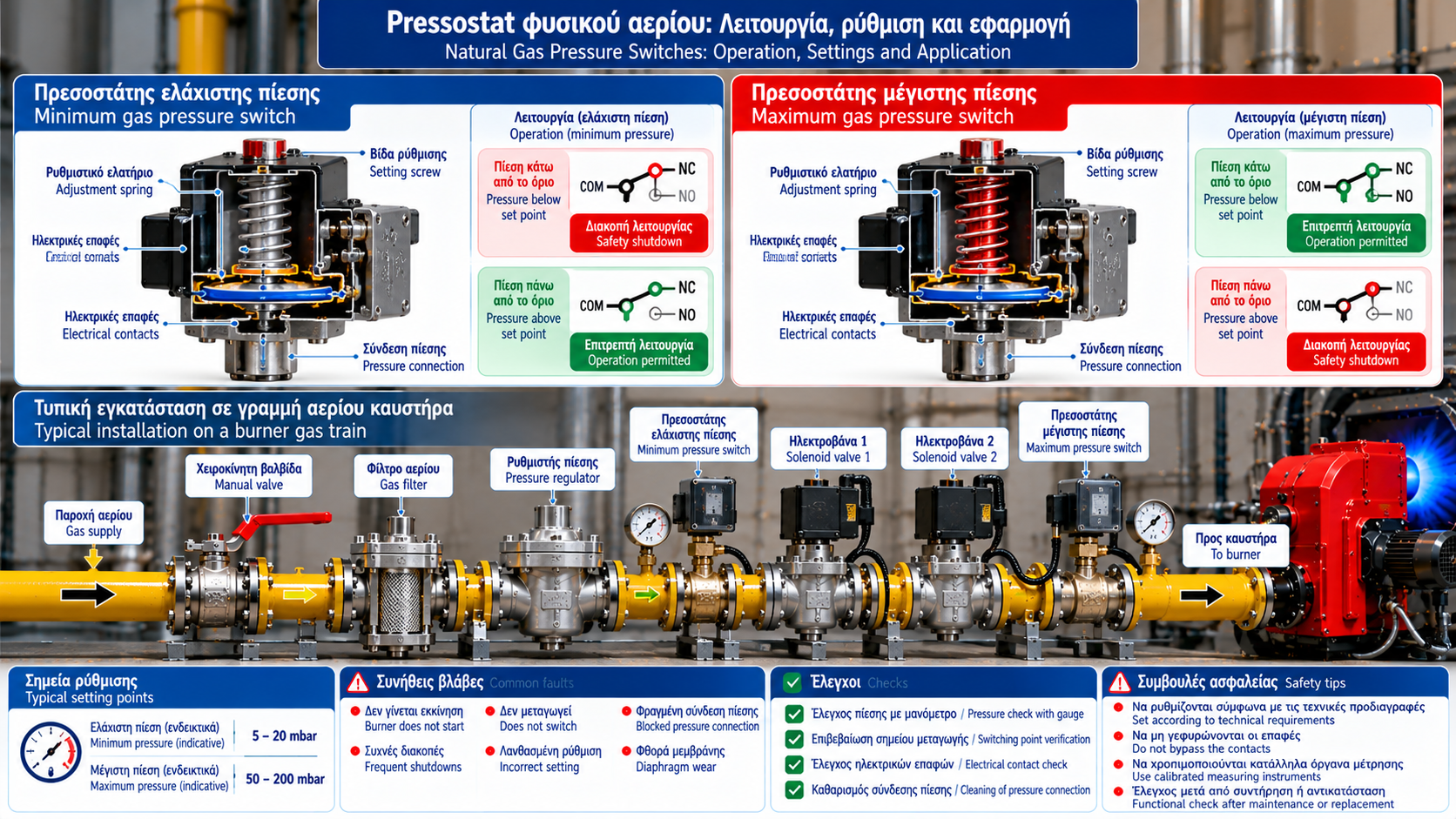
A typical mechanical gas pressure switch contains a diaphragm, an adjustable spring and an electrical switching mechanism.
Gas pressure acts on the diaphragm against the spring force.
When the pressure reaches the specified switching point, the mechanism changes the state of the electrical contact.
The burner management system uses this signal as part of its operating permissives and safety interlocks.
2. Minimum Gas Pressure Switch
A minimum gas pressure switch monitors the lower acceptable gas pressure limit.
If pressure falls below the specified threshold, the switch changes state and the burner control system may prevent startup or initiate shutdown.
Potential causes of low gas pressure include insufficient supply pressure, clogged gas filters, regulator problems, excessive pressure losses and undersized gas-train components.
The switch signal indicates a pressure condition; it does not identify the underlying cause.
3. Maximum Gas Pressure Switch
A maximum gas pressure switch monitors the upper permitted pressure limit.
If the threshold is exceeded, the control system receives a signal indicating an unacceptable operating condition.
Potential causes include regulator malfunction, incorrect settings and unexpected changes in upstream supply pressure.
Excessive gas pressure can affect gas-train components and burner performance.
4. Pressure Switch Installation
Pressure switches are installed at selected pressure monitoring points within the gas train.
The minimum pressure switch may verify adequate supply conditions, while the maximum pressure switch may monitor a designated section downstream of pressure regulation.
There is no universal installation sequence suitable for every burner.
The correct arrangement depends on the approved gas-train design, manufacturer instructions and applicable safety requirements.
5. Internal Construction
A mechanical pressure switch typically includes:
Housing and pressure connection.
Flexible diaphragm.
Adjustment spring.
Switching mechanism.
Electrical contacts.
Adjustment scale.
Electrical terminals.
The pressure acting on the diaphragm is balanced against spring force.
The difference between the actuation and reset pressures is called switching differential or hysteresis.
6. How Are Switching Settings Determined?
Switching points must be established from burner requirements, specified operating pressures and approved commissioning procedures.
They should never be changed simply to eliminate a recurring alarm.
Relevant considerations include burner pressure requirements, operating load, pressure drops, permitted operating range, switch accuracy, hysteresis and manufacturer instructions.
The adjustment scale provides a reference, but the actual switching point should be verified using an appropriate calibrated instrument and approved procedure.
7. Interaction with Burner Controls
Pressure switches form part of the burner safety and permissive system.
Before ignition, the burner controller may require confirmation of acceptable gas pressure.
During operation, loss of the required signal may cause a fuel shutdown.
The exact response and reset requirements depend on the control design and applicable safety function.
Not all pressure-related shutdowns permit automatic restart.
8. Common Faults
Burner Does Not Start
Possible causes include actual pressure outside the permitted range, faulty switch contacts, wiring problems or another active safety interlock.
Repeated Shutdowns
Pressure fluctuations under load, unstable regulator performance or marginal switching settings may be involved.
Switch Does Not Change State
Potential causes include mechanical failure, blocked pressure connections, damaged electrical contacts or pressure that does not reach the switching threshold.
Unexplained Pressure Alarm
Independent pressure measurements and review of the control sequence are required.
9. Safe Troubleshooting
Troubleshooting must be carried out by qualified and authorized personnel.
A structured assessment includes reviewing the alarm history, confirming actual gas pressure, comparing measurements at appropriate gas-train points, checking electrical contact status and verifying switching performance through an approved procedure.
Bypassing a gas pressure switch to force burner operation is unsafe and is not an acceptable corrective action.
10. Maintenance and Replacement
Maintenance may include visual inspection, examination of pressure connections, electrical checks and verification of the required switching function.
When replacing a pressure switch, confirm its pressure range, gas compatibility, maximum operating pressure, electrical ratings, switching characteristics and required approvals.
Replacement must be followed by appropriate verification of the safety function.
11. Standards and Technical References
Relevant references include:
EN 1854: Pressure sensing devices for gas burners and gas-burning appliances.
EN 676: Forced draught burners for gaseous fuels, within its scope.
Manufacturer installation, commissioning and maintenance instructions.
Conclusion
Gas pressure switches are essential monitoring devices that help prevent burner operation under unacceptable gas pressure conditions.
Correct selection, installation and switching-point verification are fundamental to reliable combustion system operation.
When a pressure alarm occurs, the objective should be to identify and correct the underlying cause rather than merely restoring burner operation.