
# Plate Heat Exchangers: Construction, Operation, Advantages and Maintenance
## Introduction
Plate heat exchangers (PHEs) are widely used to transfer thermal energy between two fluid streams. They are essential in industrial processes, hot-water systems, steam applications, manufacturing plants and water treatment facilities.
Their main advantages include a large heat transfer area within a compact footprint, flexible configurations and the possibility of servicing certain designs.
Actual performance depends on correct selection, fluid quality, operating flow rates and the condition of plates and seals.
## 1. What Is a Plate Heat Exchanger?
A plate heat exchanger transfers heat between fluid streams through thin metal plates.
The plates form a series of flow channels. In conventional indirect-contact designs, the fluids remain physically separated.
The hotter stream transfers energy through the plate wall to the colder stream.
Applications include process heating, cooling, heat recovery and phase-change duties when the exchanger is specifically designed for them.
## 2. Main Components
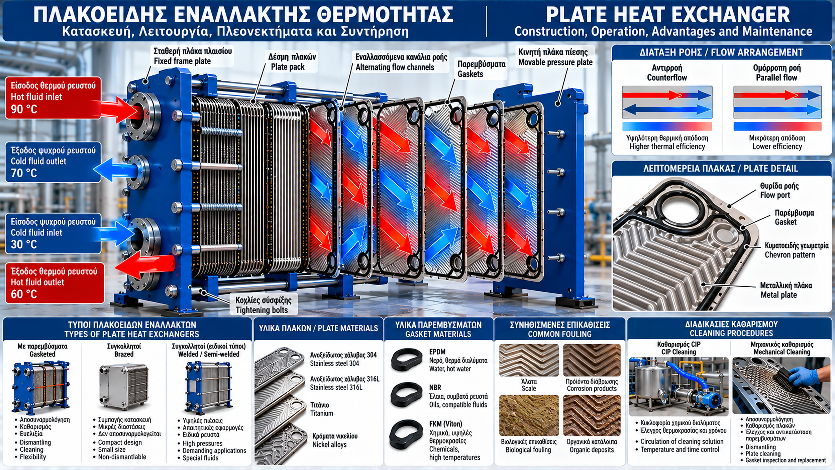
A typical gasketed plate-and-frame heat exchanger includes:
• Fixed frame plate.
• Movable pressure plate.
• Corrugated heat transfer plates.
• Sealing gaskets.
• Upper and lower carrying or guide bars.
• Tightening bolts.
• Fluid inlet and outlet connections.
Together, these components support the plate pack and establish the intended flow arrangement.
## 3. How the Plates Work
Each plate has a specially engineered corrugated pattern, often a chevron geometry.
The corrugations improve plate rigidity and influence local mixing, turbulence and convective heat transfer.
Adjacent plates create narrow fluid channels.
Heat is transferred through the plate wall without intentional mixing of the two streams.
The exact flow path depends on plate design, port arrangement and gasket configuration.
## 4. Flow Arrangement and Counterflow
Many plate exchangers use predominantly countercurrent flow, meaning the two streams move in opposite directions.
Counterflow can provide high thermal effectiveness and reduce the required heat transfer area.
However, not every plate heat exchanger uses a simple single-pass counterflow arrangement.
Multi-pass and specialized configurations must be accounted for during thermal design.
## 5. Main Types of Plate Heat Exchangers
Common designs include:
• Gasketed plate heat exchangers.
• Brazed plate heat exchangers.
• Fully welded plate heat exchangers.
• Semi-welded plate heat exchangers.
• Specialized plate-and-frame configurations.
Selection depends on fluid properties, temperature, pressure, sealing requirements and cleaning access.
## 6. Gasketed Plate Heat Exchangers
Gasketed exchangers use suitable sealing materials between plates.
Where permitted by the manufacturer, the plate pack can be dismantled for inspection, cleaning or component replacement.
Some models also allow the number of plates to be changed within the design limits of the frame.
Correct gasket selection and compliance with the specified tightening dimension are essential.
## 7. Brazed Plate Heat Exchangers
Brazed plate exchangers use permanently joined plates to form a compact assembly.
They do not rely on conventional inter-plate elastomer gaskets.
They are commonly used in compatible closed-loop systems.
They cannot be dismantled for mechanical cleaning. When approved, chemical circulation may be used to remove deposits.
Compatibility between the brazing material and the process fluid is critical.
## 8. Plate Materials
Plate materials must provide suitable heat transfer, mechanical strength and corrosion resistance.
Typical options include:
• AISI 304 stainless steel.
• AISI 316L stainless steel.
• Titanium.
• Selected nickel alloys.
Material selection must consider chloride concentration, pH, temperature, dissolved gases and other corrosive conditions.
316L stainless steel is not suitable for every chloride concentration or operating temperature.
## 9. Gasket Materials
Gaskets must withstand the process fluid, temperature and operating conditions.
Common elastomer families include:
• EPDM for selected water and hot aqueous services.
• NBR for certain oil and compatible-fluid applications.
• FKM for specific chemical and temperature requirements.
Compatibility cannot be determined from the general elastomer family alone.
The specific grade, operating limits and manufacturer approval must be checked.
## 10. Heat Transfer Duty Calculation
For a single-phase fluid with approximately constant heat capacity:
Q̇ = ṁ × cp × ΔT
Where:
Q̇ = thermal duty in kW.
ṁ = mass flow rate in kg/s.
cp = specific heat capacity in kJ/(kg·K).
ΔT = temperature change in K.
For greater accuracy, actual thermophysical properties should be used.
## 11. Practical Example
Consider a water circuit with:
Flow rate: 12 m³/h.
Inlet temperature: 75 °C.
Outlet temperature: 55 °C.
For a simplified calculation, assume water density of 1,000 kg/m³ and cp = 4.18 kJ/(kg·K).
The mass flow rate is approximately 3.33 kg/s.
Therefore:
Q̇ = 3.33 × 4.18 × 20 ≈ 279 kW.
The water circuit releases approximately 279 kW under steady conditions, assuming negligible external heat losses.
## 12. Overall Heat Transfer Coefficient
The overall heat transfer coefficient, U, describes the combined resistance to heat transfer between the two fluids.
It depends on:
• Convective coefficients on both sides.
• Plate thickness and thermal conductivity.
• Fouling resistance.
• Flow conditions and channel geometry.
A common design relationship is:
Q̇ = U × A × ΔTlm × F
Where A is the effective area, ΔTlm is the logarithmic mean temperature difference and F is the appropriate correction factor when required.
## 13. Pressure Drop
Pressure drop is a critical design and operating parameter.
Narrow channels and corrugated surfaces enhance heat transfer but also introduce hydraulic resistance.
Excessive pressure drop increases the pumping energy required.
An increase in pressure drop at comparable flow and temperature conditions may indicate channel blockage, fouling or solid accumulation.
Measured values should be compared against clean-condition reference data and manufacturer performance curves.
## 14. Fouling and Deposits
Fouling reduces heat transfer performance.
Common sources include:
• Calcium carbonate scale.
• Corrosion products.
• Suspended solids.
• Biological deposits.
• Organic process residues.
Fouling may appear as reduced heat duty, increased pressure drop or failure to achieve the required outlet temperature.
Not every deposit produces the same pressure-drop response.
## 15. Internal and External Leakage
External leaks may result from gasket deterioration, incorrect tightening or mechanical distortion.
Internal leakage may occur when plates crack or develop through-wall corrosion, allowing the two fluids to mix.
This is especially serious when one circuit contains chemicals or non-potable water.
Testing must follow approved manufacturer procedures and facility requirements.
## 16. Thermal Expansion and Mechanical Stress
Rapid temperature changes can generate thermal stress in plates and connections.
Repeated pressure fluctuations can also damage seals.
Controlled startup, water-hammer prevention and proper piping support improve reliability.
Differential pressure and temperature limits must remain within manufacturer specifications.
## 17. Cleaning in Place (CIP)
Cleaning in Place can remove suitable deposits without fully dismantling the exchanger.
An approved procedure may include:
1. Safe isolation and preparation.
2. Verification of chemical compatibility.
3. Circulation of an appropriate cleaning solution.
4. Monitoring temperature, flow and exposure time.
5. Rinsing and neutralization where required by the procedure.
6. Leak checks and controlled return to service.
Chemical selection, concentration and exposure time must be based on deposit analysis and manufacturer instructions.
## 18. Mechanical Cleaning
Gasketed plate exchangers may allow mechanical plate cleaning.
Typical steps include:
• Recording the original plate arrangement.
• Measuring the plate-pack tightening dimension before disassembly.
• Carefully removing deposits.
• Inspecting for corrosion, cracks and deformation.
• Checking or replacing gaskets.
• Correct reassembly and leak testing.
Unsuitable tools and abrasives can damage thin plate surfaces.
## 19. Tightening and Reassembly
Plate-pack tightening must never be arbitrary.
The manufacturer specifies a tightening dimension and a procedure for uniform compression.
Excessive tightening may distort the plates.
Insufficient tightening may cause leakage.
Required inspections and tests must be completed before returning the exchanger to normal service.
## 20. Performance Monitoring
Useful operating data include:
• Inlet and outlet temperatures of both streams.
• Flow rates of both circuits.
• Inlet and outlet pressures on each side.
• Control-valve positions.
• Filter condition.
• Operating hours since the last cleaning.
Comparing current results with clean-condition reference data helps identify gradual performance deterioration.
## 21. Common Failures
Typical failures include:
• Gasket leakage.
• Plate perforation.
• Channel blockage.
• Excessive pressure drop.
• Reduced thermal duty.
• Corrosion-related damage.
• Deformation from overpressure or thermal stress.
• Incorrect flow distribution.
Reliable diagnosis combines thermal, hydraulic and mechanical evidence.
## 22. Selection Criteria
Before purchasing or replacing an exchanger, determine:
1. Required thermal duty.
2. Inlet and outlet temperatures.
3. Fluid flow rates and properties.
4. Maximum and minimum operating pressures.
5. Allowable pressure drop.
6. Plate and gasket chemical compatibility.
7. Water quality and fouling potential.
8. Cleaning and maintenance requirements.
9. Available installation space.
10. Applicable regulatory requirements and manufacturer documentation.
## 23. Conclusion
Plate heat exchangers provide an efficient and compact solution for industrial heat transfer.
However, high performance requires correct material selection, suitable flow rates, acceptable pressure drop and systematic cleanliness monitoring.
Preventive maintenance, temperature and pressure trending, and properly controlled cleaning procedures can reduce failures and extend equipment life.
Thermosphere.gr — Technical knowledge for industry, heating and energy efficiency.