
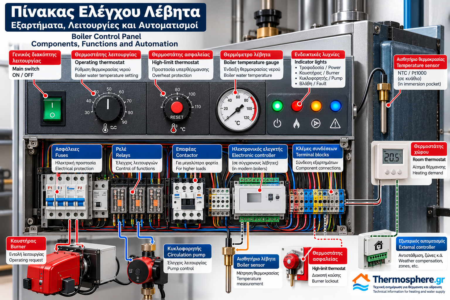
Boiler Control Panel: Components, Functions and Automation
The boiler control panel is the main operating and control interface of a heating boiler. It manages boiler activation, water temperature regulation, burner operating requests and, depending on the installation, circulation pumps and additional heating equipment.
Conventional boiler control panels commonly use mechanical thermostats, switches, indicator lights and electromechanical relays. Modern boilers often incorporate electronic circuit boards, temperature sensors and programmable control systems.
The fundamental operating principle remains the same: the controller receives information from the heating installation, evaluates operating conditions and issues commands to the appropriate components.
This technical guide explains the construction, components, operating sequence and main safety functions of heating boiler control panels.
1. What Is a Boiler Control Panel?
A boiler control panel is an electrical or electronic assembly used to operate and supervise a heating boiler.
Depending on its design, it may perform the following functions:
Boiler activation and shutdown.
Water temperature regulation.
Heating demand monitoring.
Burner operating requests.
Circulation pump control.
Temperature monitoring.
Safety limit supervision.
Operating status and fault indication.
Communication with external heating controllers.
Not every control panel provides all these functions.
Its capabilities depend on the boiler model, control architecture and installation requirements.
2. Control Panel Location
On many floor-standing boilers, the control panel is installed on the top or front of the outer casing.
Other installations use a separate electrical control cabinet in the boiler room.
Modern wall-mounted gas boilers generally incorporate an electronic controller inside the appliance.
The installation location should allow safe operation, suitable protection against moisture and appropriate maintenance access.
3. Main Operating Switch
The main operating switch enables or disables normal control panel operation.
Common positions include:
0 — OFF.
I — ON.
Some switches incorporate an indicator light.
An operating switch is not necessarily a suitable electrical isolation device.
Electrical maintenance requires proper isolation and verification of the absence of voltage by qualified personnel.
4. Operating Thermostat
The operating thermostat regulates boiler water temperature.
In traditional control panels, it may use a rotary dial with a temperature scale.
When heating is required and the boiler temperature is below the control limit, the thermostat allows the combustion system to operate.
When the selected temperature is reached, the thermostat interrupts the relevant operating request.
Restart occurs according to the thermostat differential or controller logic.
Electronic systems may perform the same function using a temperature sensor and electronic controller.
5. High-Limit Safety Thermostat
The high-limit thermostat is a protective device designed to interrupt combustion when excessive boiler water temperature is detected.
In many designs, this function is independent of the normal operating thermostat.
Some safety thermostats require manual reset.
Before resetting a safety device, the cause of overheating must be investigated and the manufacturer’s instructions followed.
Possible causes include:
Insufficient water circulation.
Circulation pump malfunction.
Incorrectly positioned valves.
Failure of the normal temperature control.
Other hydraulic or electrical faults.
Safety thermostats must never be bypassed or short-circuited.
6. Boiler Temperature Gauge
The temperature gauge displays boiler water temperature.
Traditional panels frequently use analogue gauges.
Electronic systems usually display the measured temperature on a digital screen.
Temperature indication assists operational monitoring but does not replace dedicated protective devices.
7. Indicator Lights
Indicator lights provide information about operating status.
Depending on the panel, they may indicate:
Electrical power available.
Burner operation.
Circulation pump operation.
General fault.
Safety protection activation.
Indicator colours and meanings vary between manufacturers.
They must be interpreted according to the relevant equipment documentation.
8. Relays and Contactors
Relays are electrically operated switching devices.
A conventional relay contains a coil and electrical contacts.
When the coil is energised, the contacts change state.
In boiler control panels, relays may be used for:
Burner operating requests.
Circulation pump control.
Auxiliary functions.
Fault signals.
Connections to external control systems.
Contactors may be used for larger electrical loads.
Correct component selection depends on voltage, current, load characteristics and electrical protection requirements.
9. Electrical Protection and Fuses
A boiler control panel may contain fuses or other suitable protective devices.
These protect specific electrical circuits against overcurrent or short-circuit conditions.
The installation must also include the required earthing and electrical protective arrangements.
An overcurrent protection device does not replace a high-limit thermostat or a combustion safety controller.
These are separate protective functions.
10. Connection to the Burner
On boilers with a separately mounted burner, the boiler control panel may provide electrical supply and an operating request to the burner controller.
The burner controller is responsible for the prescribed safe combustion sequence.
Depending on the burner, this may include:
Defined startup stages.
Burner fan operation.
Ignition.
Fuel valve control.
Flame supervision.
Safety shutdown following a fault.
The boiler control panel and burner safety controller are not necessarily the same device.
Their electrical interface must follow the approved manufacturer wiring diagrams.
11. Circulation Pump Control
The circulation pump moves heating water through the hydronic system.
The boiler panel may control the pump through a relay or electronic output.
Some installations activate the pump whenever heating is requested.
Other systems incorporate additional functions, including:
Minimum boiler temperature conditions.
Delayed pump shutdown.
Pump overrun to remove residual heat.
External heating controller commands.
The exact control strategy depends on the hydraulic arrangement and manufacturer requirements.
Not every circulation pump is directly controlled by the boiler panel.
12. Room Thermostat
A room thermostat monitors indoor temperature and generates a heating request when necessary.
Simple systems may use a volt-free contact, provided this is supported by the controller.
More advanced systems may use digital communication or weather-compensated control.
The room thermostat does not replace the boiler operating thermostat or its high-limit safety protection.
13. Temperature Sensors
Electronic boiler controllers use temperature sensors to monitor operating conditions.
Common technologies include:
NTC thermistors.
PTC sensors.
Resistance temperature devices such as Pt1000, where specified.
The sensor’s electrical characteristics vary with temperature.
The controller converts this information into a temperature reading or control decision.
Sensors must match the specifications of the controller.
14. Electronic Boiler Controllers
Modern boilers may use electronic circuit boards or integrated control systems.
Depending on the model, these systems may manage:
Supply water temperature.
Return water temperature.
Heating demand.
Burner modulation.
Circulation pumps.
Heating zones.
Domestic hot water production.
Outdoor temperature compensation.
Diagnostic fault codes.
Building management system communication.
Available features vary significantly between boiler models.
15. Typical Boiler Control Sequence
The following is a simplified example of a conventional boiler operating sequence.
Step 1 — Activation
Electrical power is supplied and the controller is enabled.
Step 2 — Heating Demand
A room thermostat or external controller requests heating.
Step 3 — Temperature Evaluation
The operating thermostat or electronic controller determines whether heat production is required.
Step 4 — Permissive Conditions
The applicable safety devices must permit operation.
Step 5 — Burner Request
The boiler controller sends an operating request to the burner control system.
Step 6 — Water Circulation
The circulation pump operates according to the installed control strategy.
Step 7 — Temperature Setpoint Reached
When the required temperature is reached, the combustion request is interrupted or adjusted, depending on the system.
Step 8 — Standby
The controller waits until further heat production is required.
This sequence is illustrative and must not be treated as a universal operating diagram.
16. Common Boiler Control Panel Faults
The Control Panel Does Not Power On
Possible causes include loss of electrical supply, protective device operation or an internal electrical fault.
The Burner Does Not Start
Possible causes include no heating demand, the boiler already being at its temperature setpoint, an activated protective device or a burner fault.
The Circulation Pump Does Not Operate
The problem may involve the control system, electrical supply, pump itself or the conditions required for pump activation.
A Temperature Sensor Fault Appears
Potential causes include sensor failure, wiring damage or incorrect sensor compatibility.
The High-Limit Thermostat Trips
The cause of overheating and the water circulation conditions must be investigated before resetting the device.
17. Inspection and Maintenance
Technical inspection may include:
Visual examination of the control panel.
Checking wiring condition.
Inspecting terminals.
Looking for moisture or overheating.
Verifying thermostat operation.
Checking indicator lights.
Testing relay outputs.
Checking temperature sensors.
Verifying the operation of protective devices.
Electrical testing and safety verification must be performed by competent personnel using appropriate procedures and instruments.
Safety thermostats, interlocks and other protective devices must never be bypassed.
18. Conventional vs Electronic Boiler Control Panels
Feature | Conventional Panel | Electronic Panel |
Temperature regulation | Mechanical thermostat | Sensor and controller |
Indication | Lights and analogue instruments | Display and fault codes |
Operating logic | Electromechanical | Programmed electronic logic |
Burner output control | Depends on burner arrangement | Modulation where supported |
Fault diagnostics | Limited indications | More detailed, model-dependent |
Communication | Basic electrical contacts | Digital communication where supported |
Electronic controllers often provide more advanced functionality.
However, safe operation depends on the complete system design, including protective devices and correct installation.
Conclusion
The boiler control panel is a fundamental part of a heating installation.
It combines operating controls, water temperature regulation, burner commands, circulation pump management and supervision of protective devices.
Understanding its components helps technicians identify the operating sequence and distinguish control panel faults from burner or hydraulic system problems.
The actual operation and electrical connections must always be verified against the specific manufacturer’s wiring diagram and technical documentation.
This article is intended for technical information. Electrical work, control modifications and safety testing must be performed by appropriately qualified personnel.
Thermosphere.gr — Technical information for heating and water supply.