
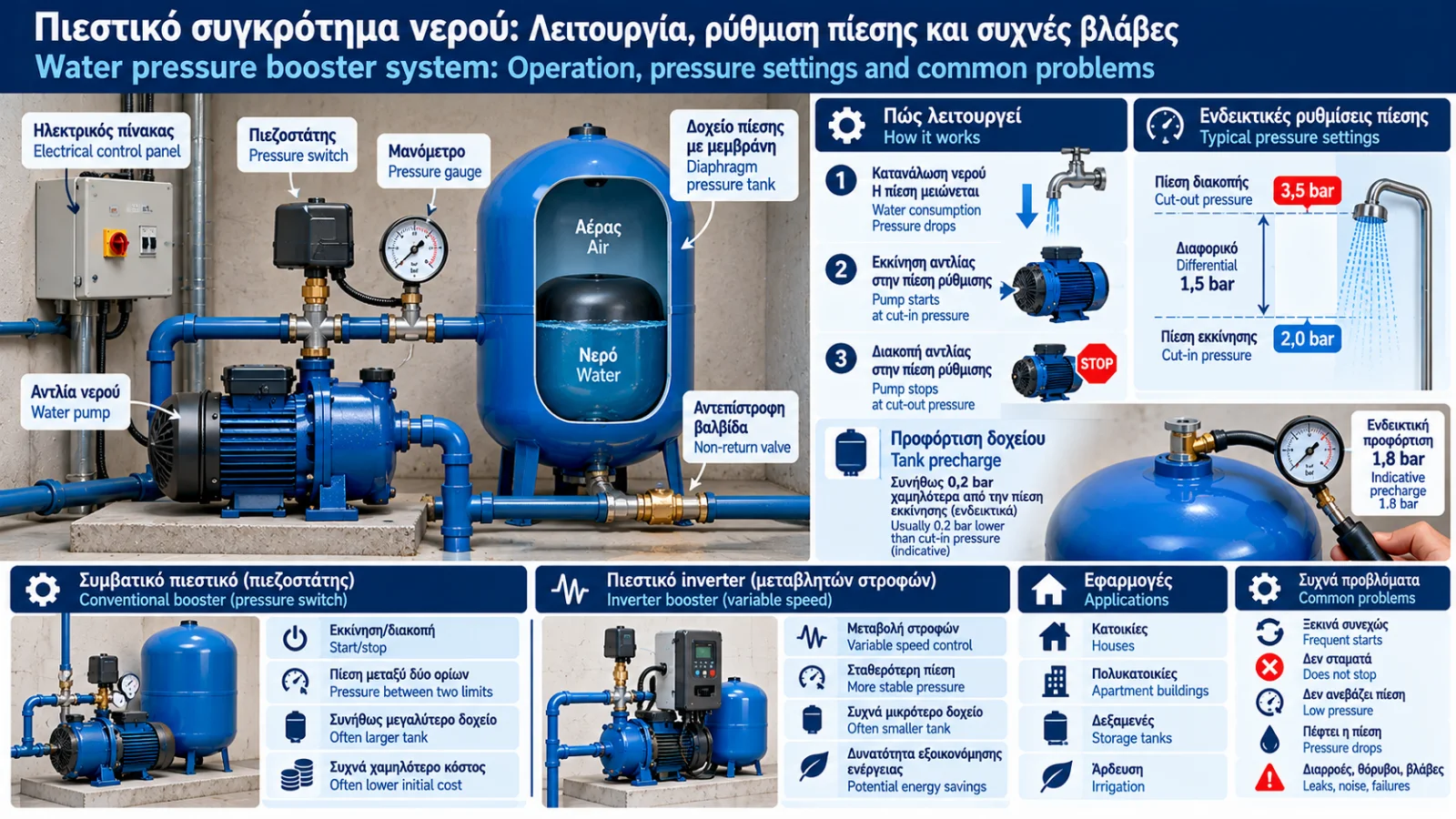
Water Pressure Booster Systems: Operation, Pressure Settings and Common Problems
A water pressure booster system is essential in installations where the available water pressure is insufficient to supply fixtures reliably.
These systems are used in houses, apartment buildings, commercial properties and installations supplied from storage tanks.
Their purpose is to deliver the required water flow and pressure by starting, stopping or controlling pumps according to demand.
However, reliable operation depends on more than the pump itself. The pressure switch, pressure vessel, air precharge, control equipment and hydraulic characteristics all affect performance.
This Thermosphere.gr guide explains how booster systems work, how their main settings are determined and which faults occur most frequently.
1. What Is a Water Pressure Booster System?
A pressure booster is an assembly that uses one or more pumps and suitable controls to maintain adequate pressure in a water distribution network.
A conventional booster system may contain:
Water pump.
Diaphragm pressure tank.
Pressure switch.
Pressure gauge.
Non-return valve.
Connecting pipes and fittings.
Electrical controls and protective devices.
More advanced installations may include multiple pumps, pressure sensors, electronic controllers and variable-frequency drives.
The exact arrangement depends on the system design.
2. How Does a Conventional Booster Work?
In a typical pressure-switch-controlled system with a pressure tank, operation occurs in cycles.
When a tap opens, water may initially be supplied from the pressure tank.
As water is consumed, system pressure falls.
When it reaches the preset cut-in pressure, the pressure switch starts the pump.
The pump supplies the network and, provided its capacity is sufficient, gradually increases pressure.
When pressure reaches the cut-out setting, the pressure switch stops the pump.
The cycle repeats according to water demand.
Important: If water demand exceeds the flow the pump can deliver at the required head, the system may not reach cut-out pressure while consumption continues.
3. What Is a Pressure Switch?
A pressure switch starts or stops a pump according to measured pressure.
In conventional mechanical designs, pressure acts on a diaphragm or piston and spring mechanism that operates electrical contacts.
Two settings are particularly important:
Cut-in pressure: The pressure at which the pump starts.
Cut-out pressure: The pressure at which the pump stops.
The difference between these settings is known as the pressure differential.
For example, a booster may be configured with:
Cut-in: 2.0 bar.
Cut-out: 3.5 bar.
Differential: 1.5 bar.
These are illustrative settings, not universal recommendations.
4. Why Is a Pressure Tank Needed?
A pressure tank stores a limited quantity of water under pressure using compressed air or gas as an elastic medium.
In common diaphragm-type tanks, a diaphragm or bladder separates water from the gas.
The tank helps:
Reduce frequent pump starts.
Supply small quantities of water without immediate pump operation.
Improve system operation.
Moderate certain pressure fluctuations.
The tank does not generate pressure independently and does not replace the pump.
A tank with a nominal capacity of 50 litres does not necessarily provide 50 litres of usable water between pump starts.
Actual drawdown depends on operating pressures, precharge and tank characteristics.
5. What Is Tank Air Precharge?
Precharge is the gas pressure inside the tank when the water side is completely depressurised.
In many conventional pressure-switch-controlled systems, precharge is set slightly below the cut-in pressure.
A commonly used illustrative setting is approximately 0.2 bar below cut-in, provided this is consistent with manufacturer instructions.
For example:
Cut-in pressure: 2.0 bar.
Illustrative precharge: 1.8 bar.
This is not a universal setting for every tank or system. Manufacturer specifications take priority.
Precharge should not be assessed while the water side remains pressurised, because the reading may be misleading.
6. How Is Precharge Checked?
Precharge should be checked using a safe procedure by appropriately trained personnel.
The general principle is:
Safely isolate the electrical supply.
Isolate the tank where the installation allows.
Release pressure from the water side.
Confirm that the hydraulic side is depressurised.
Measure air pressure at the designated valve.
Compare the reading with tank specifications and system settings.
Any air adjustment must remain within permitted limits.
If water emerges from the air valve, this may indicate diaphragm or bladder failure, depending on the tank design.
7. How Is a Pressure Switch Adjusted?
Many mechanical pressure switches have adjustments affecting cut-in pressure and the operating differential.
However, the function of individual springs and adjustment screws varies by model.
There is no universally safe instruction such as turning one screw clockwise and another anticlockwise.
Adjustments must account for:
The specific pressure switch manual.
Pump performance curve.
Pipework and component pressure ratings.
Permissible system pressure.
Pressure tank precharge.
Fixture pressure requirements.
Electrical contacts inside a pressure switch may carry hazardous voltage.
Never open or adjust an electrical pressure switch while it is energised.
8. How Are Cut-In and Cut-Out Pressures Selected?
Suitable settings are determined by the installation's hydraulic requirements.
Cut-in pressure must ensure adequate pressure at the most demanding point of use.
Cut-out pressure must remain:
Within tank and pipework pressure ratings.
Within the pressure switch operating range.
Within pump capabilities.
Below levels that would cause excessive system pressure.
For example, if the highest fixture is 10 metres above the booster, elevation alone accounts for approximately 1 bar of pressure difference.
Required residual fixture pressure and pipe friction losses must also be considered.
Therefore, a cut-in pressure of 1.5 bar may be insufficient for a particular installation even if the pressure gauge near the pump appears to show a reasonable value.
9. How Much Usable Water Does a Pressure Tank Provide?
A tank's nominal volume is not the same as the volume of water delivered between cut-out and cut-in pressures.
For an ideal tank where gas compression is approximately isothermal, an approximate relationship can be used.
Let:
V = nominal tank volume.
P₀ = absolute precharge pressure.
P₁ = absolute cut-in pressure.
P₂ = absolute cut-out pressure.
Then the theoretical drawdown is:
ΔV ≈ V × P₀ × (1/P₁ − 1/P₂)
This assumes appropriate operating conditions and that all pressures are expressed as absolute values.
Near sea level, an approximate conversion from gauge pressure to absolute pressure is obtained by adding 1 bar.
Example
Consider a 50 L tank with:
Precharge: 1.8 bar(g), approximately 2.8 bar(a).
Cut-in: 2.0 bar(g), approximately 3.0 bar(a).
Cut-out: 3.5 bar(g), approximately 4.5 bar(a).
Calculation:
ΔV ≈ 50 × 2.8 × (1/3.0 − 1/4.5)
ΔV ≈ 15.6 L
Under these simplified conditions, the 50-litre tank delivers approximately 15.6 litres between cut-out and cut-in.
Actual drawdown may differ due to construction, gas behaviour and operating limitations.
10. Why Does the Booster Start Too Frequently?
Frequent starting is one of the most common booster problems.
Possible causes include:
Incorrect or insufficient tank precharge.
Damaged diaphragm or bladder.
Undersized pressure tank.
Excessively narrow pressure differential.
Water leaks.
Faulty non-return valve.
Pressure switch malfunction.
This behaviour is often called short cycling.
Repeated starts can increase stress on the motor and electrical components.
Diagnosis should be based on measurements rather than random adjustment changes.
11. Why Won't the Booster Stop?
If a pump runs continuously without reaching cut-out pressure, possible causes include:
High water demand.
Leakage.
Insufficient water supply.
Blocked filter.
Air entering the suction line.
Worn impeller.
Excessively high cut-out setting.
A pump that cannot meet the required head.
In some cases, the pump is physically unable to achieve the selected pressure.
Increasing the pressure switch setting will not solve this problem.
If dry running or overheating is suspected, the system should be safely taken out of service until inspected.
12. Why Does Pressure Fall When No Water Is Being Used?
If all taps are closed but system pressure continues to fall, investigate:
Hidden leaks.
Toilet cisterns or appliances drawing water.
A leaking non-return valve.
Leakage at booster components.
Faulty hydraulic connections.
A defective non-return valve may allow water to flow back towards the storage tank.
Pressure then decreases, potentially restarting the pump without visible water consumption.
13. How Does an Inverter Booster Work?
A variable-speed booster normally uses a pressure sensor and electronic controller.
The controller compares actual pressure with a target and adjusts pump motor speed.
When demand increases, speed may increase.
When demand decreases, speed may reduce.
This allows pressure control with smaller fluctuations when the system is correctly designed.
Some variable-speed boosters use small pressure tanks, while others require arrangements specified by the manufacturer.
Control strategies differ between products.
14. Conventional Booster Versus Inverter Booster
Feature | Conventional booster | Inverter booster |
|---|---|---|
Control | Start/stop | Variable motor speed |
Pressure | Between two thresholds | Usually near a selected setpoint |
Pressure tank | Often larger | Often smaller, depending on design |
Electronics | Usually simpler | More complex |
Initial cost | Often lower | Often higher |
Energy efficiency | System-dependent | Potential savings under suitable conditions |
Selection depends on demand variability, pressure requirements, cost and maintenance considerations.
A conventional booster may be an appropriate and economical solution for a small installation.
A variable-speed system may offer advantages where demand varies significantly.
15. What Is Dry-Running Protection?
Dry running occurs when a pump operates without an adequate water supply.
Possible causes include:
Empty storage tank.
Low well water level.
Suction failure.
Closed or blocked supply line.
Depending on pump design, dry running can cause overheating, seal damage and other failures.
Protection methods include:
Float switches.
Level electrodes.
Pressure or flow sensors.
Electronic pump controllers.
Dedicated inverter protection functions.
The appropriate method depends on the installation.
16. What Size Pressure Tank Is Needed?
Pressure tank sizing should not be based solely on pipe diameter or pump motor power.
Important parameters include:
Required flow rate.
Cut-in and cut-out pressures.
Permitted number of starts.
Desired minimum running time.
Precharge.
Manufacturer instructions.
In conventional systems, greater usable water volume can reduce pump starts.
However, an unnecessarily large tank is not always required.
Variable-speed systems may have substantially different tank requirements.
17. Booster System Maintenance
Depending on the installation, routine maintenance may include:
Leak inspection.
Operating pressure checks.
Precharge verification according to the manual.
Tank and diaphragm inspection.
Non-return valve inspection.
Filter checks.
Noise and vibration assessment.
Dry-running protection tests.
Electrical protection checks by qualified personnel.
Inverter settings verification where applicable.
Maintenance frequency depends on manufacturer recommendations, usage conditions and system criticality.
18. Common Adjustment Mistakes
Excessively High Cut-Out Pressure
The pump may run continuously if it cannot achieve the selected pressure.
Incorrect Precharge
Usable tank drawdown may decrease, increasing the number of starts.
Very Narrow Pressure Differential
This can cause frequent cycling.
Ignoring Elevation
Pressure at the booster is not the same as pressure at a higher floor.
Ignoring the Pump Curve
The selected pressure may be impossible to achieve at the required flow.
Bypassing Protective Devices
Disabling dry-running or electrical protection can create serious equipment and safety risks.
19. Frequently Asked Questions
What Pressure Should a Water Booster Be Set To?
There is no universal setting. Required pressure depends on elevation, fixture requirements, friction losses and equipment ratings.
What Air Pressure Should a Booster Tank Have?
In many conventional systems, precharge is slightly below cut-in pressure, but manufacturer instructions must be followed.
Why Does My Booster Start Every Few Seconds?
Possible causes include incorrect precharge, diaphragm failure, insufficient tank capacity, leaks or incorrect settings.
Why Doesn't My Booster Build Pressure?
Possible causes include suction problems, insufficient water supply, pump wear, leakage or excessive system head requirements.
Is an Inverter Booster Better?
It may provide more stable pressure and energy savings in suitable applications, but it is not automatically the best option for every installation.
Does an Inverter Booster Need a Pressure Tank?
Many systems require a small tank or another specific arrangement according to manufacturer instructions.
Can I Connect a Booster Directly to the Public Water Main?
This depends on local water utility rules and backflow protection requirements. Direct connection must not be assumed to be permitted.
Conclusion
A water pressure booster is an integrated pressure-control system rather than simply a pump.
Reliable operation depends on the correct interaction between the pump, pressure switch, pressure tank and protective devices.
Settings must be based on actual system requirements, pump capabilities and component pressure ratings.
Correct cut-in and cut-out settings, appropriate tank precharge and adequate dry-running protection are essential to reliable booster operation and long equipment life.
Technical References and Further Reading
Hydraulic Institute: Pump operating and selection principles — https://www.pumps.org/
Europump: Technical resources for pumping systems — https://www.europump.net/
Grundfos: Pressure booster and pump control guidance — https://www.grundfos.com/
KSB: Pump and hydraulic system technical information — https://www.ksb.com/
EN 806: Specifications for installations inside buildings conveying water for human consumption.
EN 1717: Protection of potable water installations against backflow contamination.
EN 13831: Closed expansion vessels with built-in diaphragms for installation in water systems.
General references do not replace the manual for the specific pressure switch, pressure tank, pump or inverter.
Safety note: Before any intervention, safely isolate electrical power and release hydraulic pressure. Electrical pressure switch adjustments and work on pressurised vessels must be performed by appropriately trained personnel.
Thermosphere.gr — Technical knowledge for water supply and building systems.