
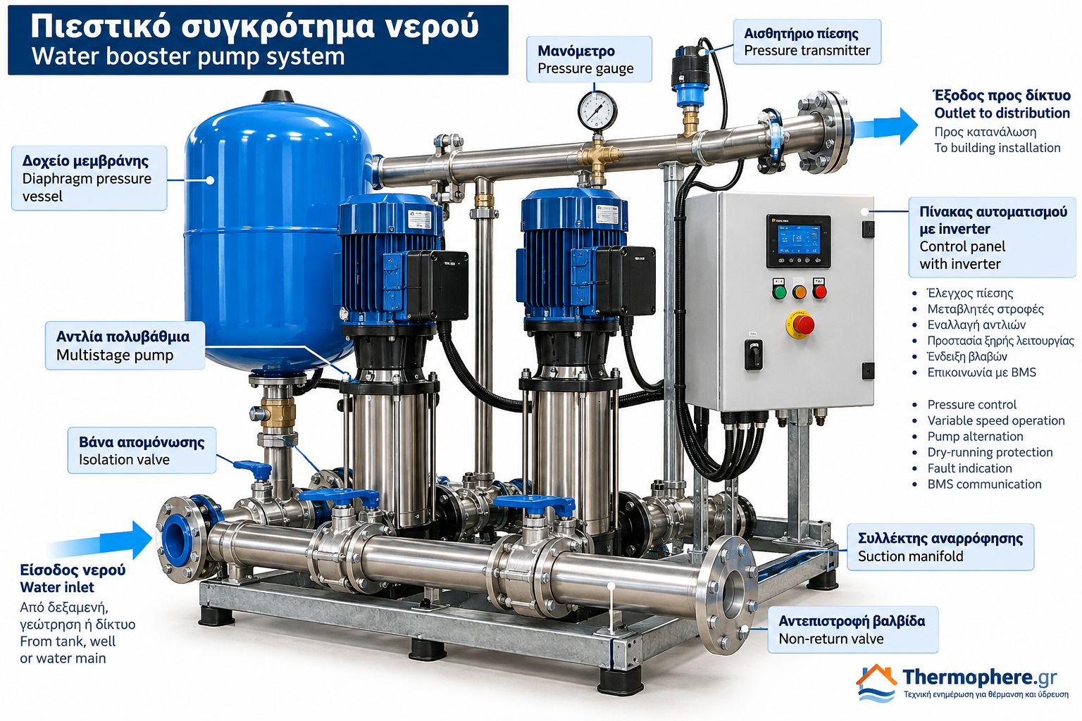
Water Booster Pump Systems: How They Work, Types and Correct Selection
Adequate and stable water pressure is essential for the reliable operation of domestic, commercial and industrial water supply installations.
In residential buildings, apartment complexes, hotels and commercial facilities, the available pressure from the incoming supply or storage tank may be insufficient to meet demand, particularly at elevated or hydraulically remote outlets.
Water booster pump systems are designed to overcome these limitations by providing the required water flow and pressure throughout the distribution network.
Selecting a booster system involves more than choosing a pump with a high motor power rating or maximum discharge pressure. Proper engineering requires an assessment of peak water demand, total dynamic head, pipe friction losses, suction conditions and the operating characteristics of the pumps.
What is a water booster pump system?
A water booster pump system is an integrated pumping arrangement consisting of one or more pumps, controls and associated hydraulic components.
Its purpose is to increase and maintain sufficient water pressure within a distribution network.
Depending on the installation, the system may receive water from a storage tank, a break tank, a suitable independent water source or an incoming water main where direct connection is explicitly permitted.
Direct suction from a public water main must not be assumed acceptable. Local water utility requirements and applicable backflow prevention regulations may require an intermediate break tank and other protective measures.
Main components of a booster pump system
1. Pumps
The pumps provide the hydraulic energy needed to deliver water at the required pressure and flow rate.
Small domestic systems frequently use a single centrifugal or multistage pump.
Larger installations may use two or more pumps operating in parallel.
Vertical multistage centrifugal pumps are common in commercial booster applications because they can provide relatively high discharge head with suitable hydraulic efficiency.
2. Electric motors
Electric motors drive the pumps and must be selected according to the required operating conditions.
Motor sizing must account for pump efficiency, absorbed power, the permitted operating range and the manufacturer’s recommendations.
3. Pressure switches and pressure transmitters
Conventional fixed-speed booster systems commonly use pressure switches to start and stop pumps at predefined pressure levels.
Variable-speed booster systems typically use electronic pressure transmitters to provide continuous feedback to the controller.
The controller then adjusts motor speed to maintain the selected pressure setpoint.
4. Diaphragm pressure vessels
A diaphragm pressure vessel stores a limited volume of water under pressure and helps reduce excessive pump cycling.
The required vessel capacity depends on the operating pressures, pump control method, allowable start frequency and system demand.
Variable-speed systems may use smaller vessels than conventional installations, but a pressure vessel is not automatically unnecessary.
5. Control panels
The control panel manages pump operation and protection.
Depending on the configuration, it may provide:
Motor protection.
Pressure regulation.
Pump alternation.
Sequential pump staging.
Dry-running protection.
Fault indication and diagnostics.
Communication with building management systems.
6. Manifolds, valves and instruments
Multi-pump booster systems commonly include shared suction and discharge manifolds.
Non-return valves prevent unwanted reverse flow, while isolation valves allow maintenance without dismantling the entire installation.
Pressure gauges and electronic sensors enable operating pressure to be monitored.
How does a conventional fixed-speed booster work?
A conventional booster system operates between predefined start and stop pressures.
When a water outlet opens, water consumption causes the system pressure to decrease.
Once the pressure reaches the start threshold, the pressure switch activates the pump.
The pump delivers water to the network. When demand decreases or stops, system pressure rises.
At the upper pressure threshold, the pump switches off.
For example:
Pump start pressure: 2.0 bar.
Pump stop pressure: 3.5 bar.
These values are illustrative only. Actual settings must reflect the installation requirements, component pressure ratings and manufacturer specifications.
One limitation of fixed-speed operation is that pressure varies between the start and stop settings.
Incorrect pressure vessel sizing or low intermittent demand may also cause frequent pump starts.
How does a variable-speed booster pump system work?
Variable-speed booster systems use a variable frequency drive (VFD), often called an inverter, to adjust pump rotational speed according to water demand.
A pressure transmitter continuously measures the system pressure.
The controller compares the measured pressure with the selected setpoint and adjusts motor speed accordingly.
As demand increases, pump speed rises.
As demand decreases, pump speed is reduced.
This allows the system to maintain relatively stable pressure within its hydraulic and control limits.
Advantages of variable-speed systems
Variable-speed booster systems can provide:
Reduced pressure fluctuations.
Improved adaptation to changing demand.
Potential energy savings under suitable operating conditions.
Smoother motor acceleration and deceleration.
Advanced monitoring and protection functions.
Energy savings are application-dependent.
They are influenced by the system’s static head, friction losses, pump efficiency, demand profile and control strategy.
A VFD does not guarantee the same percentage of energy savings in every installation.
Main types of booster pump systems
Single-pump booster systems
Single-pump systems are commonly used in houses, small buildings and applications with relatively limited water demand.
They can provide an effective solution when the selected pump covers the required flow and pressure.
Multi-pump booster systems
Multi-pump systems use two or more pumps, generally connected in parallel.
They are suitable for installations with higher or strongly variable demand.
Depending on the design, the control system can alternate pumps, stage additional pumps or combine fixed-speed and variable-speed operation.
Multi-pump systems may also provide redundancy when a standby pump is specifically included and correctly sized.
Two installed pumps do not automatically provide full redundancy. The available standby capacity must be verified.
Fixed-speed booster systems
Fixed-speed systems operate their pumps at nominal rotational speed.
Pressure regulation is achieved through start-stop control or pump staging.
Variable-speed booster systems
Variable-speed systems adjust one or more pump speeds to match changing demand and regulate pressure.
How to select the correct water booster pump system
Correct selection primarily depends on two hydraulic parameters:
Required flow rate, Q.
Required total dynamic head, H.
Both values must be evaluated together at the actual design duty point.
A pump’s maximum head and maximum flow rate are generally not available simultaneously.
Determining the required flow rate
Flow rate describes the quantity of water delivered per unit of time.
Common units include cubic metres per hour (m³/h) and litres per minute (L/min).
The required design flow should be determined from the expected simultaneous demand of the connected plumbing fixtures and equipment.
Simply adding the maximum flow rates of every outlet may significantly overestimate demand because not all fixtures are normally used at the same time.
Larger installations require an appropriate peak demand calculation based on applicable standards, regulations and the building’s usage profile.
Calculating total dynamic head
The required pump head depends on several factors:
Elevation difference between the water source and the critical outlet.
Required residual pressure at the critical outlet.
Pipe friction and fitting losses.
Available pressure at the pump inlet.
For a simplified arrangement with consistent reference points:
Required pump head = Elevation head + Required residual pressure head + Friction losses − Available inlet pressure head
All terms must be expressed in equivalent metres of water column.
A complete hydraulic assessment may also need to account for velocity head and the precise locations of the pressure reference points.
Practical pump selection example
Consider a water supply installation with the following design requirements:
Required flow rate: 3 m³/h.
Elevation difference: 12 m.
Required residual pressure: 2 bar.
Calculated distribution losses: 8 m.
Available inlet gauge pressure at the reference point: 0 bar.
Using the approximate conversion:
1 bar ≈ 10.2 metres of water column
The required residual pressure head is:
2 × 10.2 = 20.4 m
Therefore:
H = 12 + 20.4 + 8 = 40.4 m
The required pump duty point is approximately:
Q = 3 m³/h at H = 40.4 m
The selected pump must be capable of delivering this flow rate at the calculated head.
A pump advertised with a maximum head of 45 m may still be unsuitable if its available head falls below 40.4 m at 3 m³/h.
This is why manufacturer performance curves must be checked.
Understanding the pump performance curve
A pump performance curve describes the relationship between flow rate and developed head.
For most centrifugal pumps, the available head decreases as flow rate increases.
The actual operating point is determined by the intersection of the pump curve and the system resistance curve.
The following characteristics should be reviewed during selection:
Hydraulic efficiency.
Absorbed power.
Best efficiency point (BEP).
Allowable operating range.
Suction requirements.
Performance at minimum and maximum demand.
Oversized pumps may cause unnecessary energy consumption, excessive pressure, frequent cycling and unstable operation.
Undersized pumps may fail to provide adequate pressure during peak consumption.
What is NPSH and why is it important?
Net Positive Suction Head (NPSH) is an important parameter for assessing the risk of pump cavitation.
Cavitation can occur when local liquid pressure falls sufficiently for vapour bubbles to form.
When these bubbles collapse in higher-pressure regions, they can produce noise, vibration, reduced performance and mechanical damage.
The available NPSH of the installation (NPSHa) must exceed the pump’s required NPSH (NPSHr), with an appropriate engineering margin.
The available NPSH depends on factors such as:
Water level in the supply tank.
Atmospheric pressure.
Water temperature.
Suction pipe friction losses.
Pump elevation relative to the water source.
Correct suction design is therefore essential, even when the pump has sufficient nominal head and flow capacity.
Single-pump or multi-pump configuration?
The appropriate configuration depends on the expected demand range and required service continuity.
A properly selected single-pump booster may be entirely adequate for a small residential installation.
A hotel or large apartment building may experience substantial demand fluctuations throughout the day.
In such cases, multiple pumps can offer improved staging, load sharing, pump alternation and redundancy.
However, standby capacity must be explicitly specified.
A system containing two pumps is not necessarily capable of meeting full demand when one pump is unavailable.
Common booster pump selection mistakes
Selecting a pump only by motor power
Two pumps with the same motor power rating may have significantly different performance curves and efficiencies.
Selecting by maximum pressure
Maximum pump head usually occurs at zero or very low flow and does not represent the actual duty point.
Ignoring pipe losses
Undersized pipework, long pipe runs, filters, valves and fittings can produce significant pressure losses.
Incorrect pressure vessel sizing
An undersized or incorrectly precharged vessel can cause excessive cycling and unstable pressure.
Neglecting suction conditions
Even a correctly sized pump may experience cavitation or poor operation if suction conditions are inadequate.
Missing protective devices
Dry running, electrical faults and excessive pressure must be addressed through suitable protection and control measures.
Essential installation considerations
A correctly selected booster system can still perform poorly if installed incorrectly.
Important installation requirements include:
Proper suction pipe sizing and arrangement.
Prevention of air ingress.
Adequate water supply to the pump.
Dry-running protection.
Secure mounting and vibration control.
Appropriate electrical protection and earthing.
Correct pressure settings.
Overpressure protection.
Sufficient maintenance access.
Suitable materials for drinking water applications.
Installation and electrical connections should be performed by qualified personnel in accordance with manufacturer instructions and applicable regulations.
Conclusion
Water booster pump systems are essential for providing adequate flow and pressure in water distribution installations.
Correct selection requires an accurate assessment of design flow rate, total dynamic head, pump performance curves, suction conditions and control requirements.
Both conventional fixed-speed systems and variable-speed booster systems can provide reliable performance when properly engineered.
The quality of a booster pump installation is determined not by the nominal power of its pumps, but by how accurately the system matches the hydraulic requirements of the network.
Thermosphere.gr — Technical knowledge for heating, water supply and modern plumbing systems.