
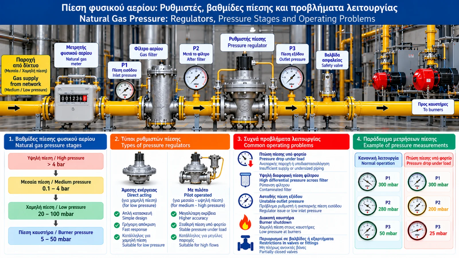
Natural Gas Pressure: Regulators, Pressure Levels and Operating Problems
Natural gas pressure is a critical parameter for safe and stable operation of industrial burners, boilers, furnaces and combustion systems.
Even correctly sized burners and gas trains may experience operational problems when supply pressure falls outside the required range.
Pressure management includes reducing network pressure to the required operating level, maintaining stability under changing demand and protecting the installation against unacceptable overpressure or underpressure conditions.
1. What Is Natural Gas Pressure?
Pressure represents force per unit area.
Common units include bar, mbar, kPa and Pa.
1 bar = 1,000 mbar = 100 kPa
1 mbar = 100 Pa
Gauge pressure is measured relative to atmospheric pressure, while absolute pressure is measured relative to absolute vacuum.
Gas density, volume and compressibility calculations require the appropriate absolute pressure.
2. Pressure Levels in Natural Gas Networks
Natural gas is transmitted and distributed through networks operating at different pressure levels.
Pressure reduction stations may be used before gas reaches the consumer.
Industrial installations may include additional pressure regulation stages according to equipment requirements.
Exact pressure classifications and limits depend on applicable regulations and standards.
There is no single pressure setting suitable for every industrial burner.
3. What Does a Gas Pressure Regulator Do?
A gas pressure regulator reduces inlet pressure to a lower outlet pressure and maintains the outlet within a specified range as flow changes.
A typical self-operated regulator may include:
Valve body.
Valve seat and throttling element.
Diaphragm.
Adjustment spring.
Mechanical linkage.
Pressure reference chamber.
Internal or external pressure sensing connection.
Construction varies by model.
4. How Does a Self-Operated Regulator Work?
The regulator responds to changes in outlet pressure.
As demand increases, outlet pressure tends to decrease. The regulator adjusts its throttling element to increase gas flow.
As demand decreases, outlet pressure tends to rise and the regulator restricts flow.
Actual behavior depends on design, available differential pressure and system dynamics.
5. Direct-Acting and Pilot-Operated Regulators
Direct-acting regulators use outlet pressure and mechanical elements such as a diaphragm and spring to control the valve.
Pilot-operated regulators use an additional pilot system to control the main regulating element.
Pilot-operated designs may offer advantages in certain high-flow or demanding control applications, but suitability depends on the model and operating conditions.
6. Inlet and Outlet Pressure
Inlet pressure is commonly identified as P1 and outlet pressure as P2.
For example, a regulator may receive gas at 1 bar(g) and deliver 100 mbar(g), provided it is designed for these conditions.
This is an illustrative example, not a recommended setting.
Selection must account for both minimum and maximum expected inlet pressure.
7. Understanding Pressure Droop
Pressure droop is the change in regulated outlet pressure as flow increases under defined conditions.
Many self-operated regulators exhibit some reduction in outlet pressure as demand increases.
Manufacturer performance curves describe this behavior.
A regulator may maintain satisfactory pressure at low flow but show significant deviation near its upper operating limit.
8. Lock-Up Pressure
Lock-up pressure is the outlet pressure reached when flow decreases to zero and the regulator closes under specified test conditions.
It may be higher than the normal flowing outlet pressure.
The allowable value is determined by the regulator specifications.
Excessive pressure rise after demand stops may indicate a malfunction or seat leakage, but requires technical assessment.
9. Regulator Creep
Regulator creep is an undesirable gradual rise in outlet pressure under no-flow conditions, commonly associated with leakage past the regulator seat.
Possible causes include:
Seat wear.
Contamination.
Mechanical damage.
Unsuitable operating conditions.
Creep must be distinguished from normal lock-up behavior.
10. Why Does Pressure Fall at High Demand?
Possible causes include:
Insufficient inlet pressure.
Undersized regulator.
Excessive piping pressure loss.
Contaminated filter.
Restriction in a valve or fitting.
Excessive combined demand.
Regulator dynamic limitations.
Diagnosis requires measurements at suitable points under known operating loads.
11. Pressure Losses Across the Gas Train
Depending on configuration, the gas supply line may contain filters, regulators, meters, isolation valves, automatic safety shut-off valves, pipes and fittings.
Each component may introduce pressure loss.
Total losses should be evaluated at maximum required flow and under the least favorable expected supply conditions.
12. Static Versus Flowing Pressure
Static pressure is measured when little or no gas is flowing.
Flowing pressure is measured while equipment is consuming gas.
An installation may have adequate static pressure but insufficient pressure at full burner load.
Static pressure alone cannot establish supply capacity.
13. Pressure Instability and Hunting
Hunting describes repeated oscillations in regulated pressure or regulator position.
Possible causes include unsuitable regulator selection, unfavorable system dynamics, rapid demand changes, incorrect sensing locations, sensing line problems and interactions between control devices.
Assessment should consider the entire installation.
14. Gas Pressure Switches
Pressure switches monitor pressure relative to specified limits.
They may be used for low-pressure supervision, high-pressure supervision and burner safety interlocks.
A pressure switch does not replace a pressure regulator.
The regulator controls pressure; the switch supervises a defined condition.
15. Overpressure Protection
Suitable installations may require additional or independent protection against unacceptable overpressure.
Depending on design, protection may include slam-shut valves, pressure relief devices where permitted, monitoring systems and backup regulation arrangements.
Selection depends on the safety assessment, allowable pressures and applicable standards.
16. What Is a Slam-Shut Valve?
A slam-shut valve is a protective device that isolates gas supply when a specified unacceptable pressure condition occurs.
Depending on the design, it may monitor overpressure, underpressure or both.
It is not intended to serve as a normal regulating valve.
Following activation, the cause must be investigated and reset must follow approved procedures.
17. Natural Gas Pressure Troubleshooting
Symptom | Possible Causes | Assessment |
|---|---|---|
Low pressure at full load | Limited supply or high losses | Flowing pressure measurements |
Normal no-flow pressure, low under load | Restriction or insufficient capacity | Evaluate pressure drops |
Gradual no-flow pressure rise | Possible regulator creep | Approved regulator inspection |
Pressure oscillation | Hunting or varying demand | Pressure trend recording |
Frequent pressure switch trips | Actual deviation or instrument fault | Review events and measurements |
Slam-shut activation | Protective condition or fault | Investigate before reset |
Disagreement between gauges | Different locations or instrument issue | Verify instruments and conditions |
These are possible diagnostic directions rather than definitive conclusions.
18. Instrumentation and Pressure Logging
Suitable pressure gauges, digital transmitters, differential pressure sensors, data loggers and SCADA/BMS systems may be used.
Instrument selection must consider range, accuracy, calibration and safety requirements.
Pressure trend data combined with burner operating status can reveal problems that a single instantaneous reading may miss.
19. Selecting a Gas Pressure Regulator
Selection criteria include:
Minimum inlet pressure.
Maximum inlet pressure.
Required outlet pressure.
Minimum and maximum flow.
Allowable outlet pressure variation.
Dynamic response characteristics.
Gas quality and composition.
Operating temperature.
Safety requirements.
Manufacturer specifications.
Connection diameter alone is not sufficient for proper selection.
20. Relevant Technical Standards
Relevant references include:
EN 334: Gas pressure regulators for inlet pressures up to 10 MPa.
EN 14382: Gas safety shut-off devices for operating pressures up to 10 MPa.
EN 88-1: Pressure regulators for gas burners and appliances within its scope.
**EN 15001