
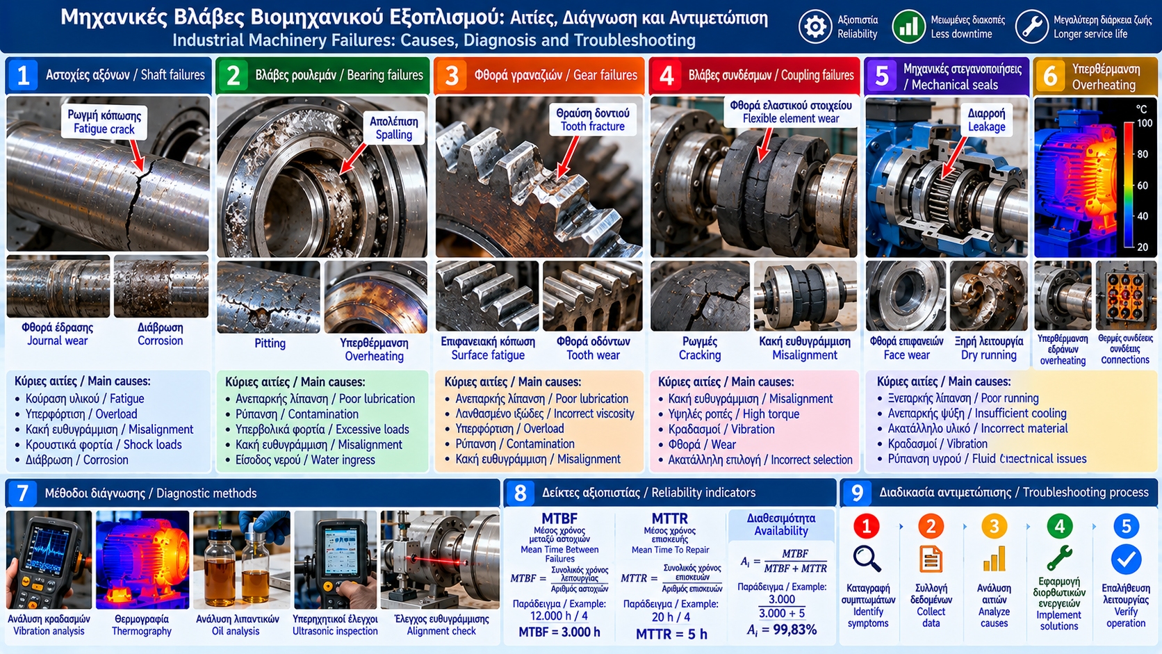
# Industrial Machinery Failures: Causes, Diagnosis and Troubleshooting
## Introduction
Mechanical failures are a major cause of unplanned downtime in industrial facilities. Pumps, electric motors, gearboxes, fans, compressors and power transmission systems operate under continuous mechanical and thermal stresses.
A failure may begin with minor bearing wear, inadequate lubrication or incorrect alignment and eventually develop into serious equipment damage.
Effective troubleshooting requires an understanding of wear mechanisms, careful assessment of symptoms and evidence-based diagnosis.
## 1. What Is a Mechanical Failure?
A mechanical failure is the loss or degradation of a component's or system's ability to perform its intended function.
It may result from:
- Friction-related wear.
- Mechanical fatigue.
- Overloading.
- Impact.
- Corrosion.
- Inadequate lubrication.
- Thermal stress.
- Incorrect installation.
- Unsuitable operating conditions.
Failure is not always sudden. It is often preceded by gradual deterioration.
## 2. Main Mechanical Failure Mechanisms
### Friction and Wear
Relative motion between surfaces can cause material loss, increased clearances and changes in machine performance.
### Mechanical Fatigue
Repeated loading can initiate and propagate cracks over time.
Fatigue failure may occur even when instantaneous stress remains below the static strength limit.
### Overloading
Overloading occurs when applied stresses exceed the component's load-bearing capacity.
### Corrosion
Chemical or electrochemical attack may reduce the thickness and strength of metallic components.
### Thermal Stress
Expansion, contraction and large temperature differences can cause deformation or cracking.
## 3. Shaft Failures
Shafts transmit torque and support rotating components.
Common failures include:
- Fatigue cracks.
- Plastic deformation.
- Fracture.
- Bearing journal wear.
- Corrosion.
- Keyway damage.
Possible causes:
- Excessive torque.
- Shock loads.
- Misalignment.
- Unsuitable geometry.
- Stress concentration.
- Bearing problems.
- Poor manufacturing or repair quality.
Cracks in critical shafts require assessment by qualified personnel before operation continues.
## 4. Fatigue and Fracture
Fatigue is associated with repeated loading cycles.
A crack may initiate at:
- Sharp section transitions.
- Keyways.
- Surface defects.
- Corrosion pits.
- Welded regions.
- Machining marks.
The crack may then propagate until the remaining effective cross-section becomes insufficient.
Fracture surface examination may reveal important evidence about the failure mechanism.
For critical components, nondestructive testing may be required, including magnetic particle, liquid penetrant or ultrasonic inspection, depending on material and geometry.
## 5. Bearing Failures
Bearings support rotating shafts and allow rotation with controlled friction.
Common failure modes include:
- Surface spalling.
- Raceway wear.
- Corrosion.
- Overheating.
- Cage damage.
- Rolling element deformation.
- Lubrication-related failure.
Causes include:
- Incorrect bearing selection.
- Excessive loads.
- Misalignment.
- Lubricant contamination.
- Water ingress.
- Incorrect mounting.
- Unsuitable internal clearance or preload.
Vibration analysis and temperature monitoring help identify problems, but definitive diagnosis may require component inspection.
## 6. Coupling Failures
Couplings transmit torque between shafts.
Depending on their design, they may accommodate limited alignment deviations.
Common problems include:
- Flexible element wear.
- Cracking.
- Loose connections.
- Fracture.
- Excessive temperature.
- Abnormal vibration.
Misalignment, high torque and sudden load changes can reduce service life.
A flexible coupling's ability to tolerate small deviations does not eliminate the need for proper alignment.
## 7. Gearbox Failures
Gearboxes change rotational speed and torque.
Typical problems include:
- Gear tooth wear.
- Surface fatigue.
- Tooth fracture.
- Bearing damage.
- Overheating.
- Oil leakage.
- Increased noise.
Possible causes:
- Inadequate lubrication.
- Incorrect lubricant viscosity.
- Contamination.
- Overloading.
- Misalignment.
- Sealing problems.
Diagnosis may involve oil analysis, vibration monitoring, temperature measurements and gear inspection.
## 8. Machinery Overheating
Excessive temperature may indicate a mechanical or operational problem.
Possible causes include:
- Insufficient lubrication.
- Excessive friction.
- Overloading.
- Reduced cooling.
- Misalignment.
- Damaged bearings.
- Unsuitable process temperature.
Temperature should be compared with manufacturer limits and operating history.
A temperature increase alone does not prove a specific failure.
## 9. Mechanical Seals and Leakage
Mechanical seals are used to limit leakage along rotating shafts.
Failures may result from:
- Dry running.
- Inadequate cooling.
- Incompatible materials.
- Excessive vibration.
- Misalignment.
- Liquid contamination.
- Incorrect installation.
Repeated seal replacement without investigating the cause may lead to recurring failures.
## 10. Vibration as a Failure Indicator
Vibration can result from:
- Imbalance.
- Misalignment.
- Mechanical looseness.
- Bearing wear.
- Gear defects.
- Resonance.
- Hydraulic excitation.
Measurements may include:
- Vibration velocity.
- Acceleration.
- Displacement.
- Frequency spectrum.
- Time waveform.
Diagnosis requires consideration of spectral patterns, rotational speed, sensor location and operating conditions.
Not every high vibration reading indicates imbalance.
## 11. Thermography for Failure Diagnosis
Thermography can help identify thermal anomalies.
Applications include:
- Bearings.
- Couplings.
- Gearboxes.
- Electric motors.
- Power transmission systems.
Interpretation requires attention to emissivity, reflections and operating load.
Thermography is a complementary method and does not replace inspection or other measurements.
## 12. Lubricant Analysis and Wear
Oil analysis may reveal:
- Metallic wear particles.
- Increased moisture.
- Viscosity changes.
- Oxidation.
- Contamination.
- Additive degradation.
Monitoring trends can help identify progressive wear.
Results should be assessed against lubricant type and machine characteristics.
## 13. Systematic Troubleshooting Procedure
A structured process includes:
1. Recording symptoms.
2. Confirming safe conditions.
3. Collecting operating history.
4. Checking load and process conditions.
5. Measuring vibration and temperature.
6. Inspecting lubrication.
7. Checking alignment and foundations.
8. Inspecting components when required.
9. Analyzing potential causes.
10. Implementing and verifying corrective actions.
The sequence should be adapted to equipment type and failure risk.
## 14. Example: Repeated Bearing Failure
An industrial fan experiences recurring bearing failures.
Replacing the bearing temporarily restores operation.
Investigation reveals:
- Increased vibration.
- Alignment deviations.
- Incorrect lubricant quantity.
- Temperature changes.
The root cause may involve several interacting factors.
Corrective action requires alignment correction, suitable lubrication and vibration verification after repair.
Replacing the same component without investigation does not ensure a permanent solution.
## 15. Root Cause Analysis (RCA)
Root cause analysis aims to identify the underlying causes of failure.
Common methods include:
- Five Whys.
- Ishikawa diagrams.
- Fault Tree Analysis.
- Maintenance history review.
- Laboratory examination of failed parts.
RCA should examine both technical and organizational factors, including inadequate procedures, insufficient training or incorrect design information.
## 16. Preventive Measures
Recommended actions include:
- Correct equipment selection.
- Operation within specified limits.
- Suitable lubrication.
- Alignment verification.
- Vibration monitoring.
- Temperature monitoring.
- Contamination control.
- Seal inspection.
- Failure history records.
- Verification of repair effectiveness.
Inspection intervals should reflect asset criticality and manufacturer recommendations.
## 17. Inspection and Repair Safety
Before intervention:
- Stop equipment safely.
- Isolate hazardous energy sources.
- Apply lockout/tagout where required.
- Depressurize and drain.
- Check temperature.
- Prevent unintended rotation.
- Assess hazards from chemicals or hot liquids.
- Use suitable personal protective equipment.
Inspection of operating machinery must follow approved safe procedures and appropriate guarding requirements.
## 18. When Should a Component Be Replaced?
The decision depends on:
- Extent of damage.
- Feasibility of safe repair.
- Component criticality.
- Manufacturer tolerances.
- Risk of repeated failure.
- Downtime cost.
- Spare-parts availability.
Continued operation with cracks, excessive clearances or other serious defects may create substantial risks.
## Conclusion
Industrial machinery failures are associated with fatigue, wear, lubrication, alignment, temperature and actual operating conditions.
Effective diagnosis requires a combination of measurements, technical inspection and root cause analysis.
Systematic monitoring and appropriate maintenance reduce recurring failures, control costs and improve plant reliability.
Thermosphere.gr – Technical Knowledge for Professionals.