
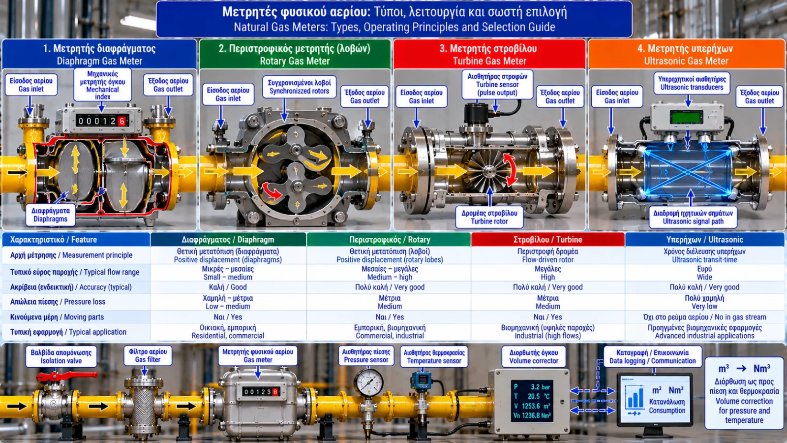
Natural Gas Meters: Types, Operating Principles and Selection Guide
Reliable natural gas measurement is essential for consumption monitoring, energy cost management and performance assessment in industrial facilities.
In boiler rooms, steam generation plants and industrial combustion systems, a gas meter is more than a device recording cubic metres. It may form part of a metering system incorporating pressure and temperature sensors, electronic volume correctors and remote monitoring.
Correct meter selection requires understanding measurement technology, flow range, operating conditions and accuracy requirements.
1. What Does a Natural Gas Meter Measure?
Most conventional gas meters measure the volume passing through the instrument at the actual measurement conditions.
Readings are commonly expressed in cubic metres (m³).
Gas volume, however, depends on pressure and temperature.
Important distinctions include:
m³: Volume at actual measurement conditions.
Nm³: Volume converted to explicitly defined normal reference conditions.
Sm³: Volume converted to explicitly defined standard reference conditions.
Normal and standard reference conditions are not necessarily identical across applications. The reference temperature and pressure must be stated.
Some advanced meters may provide additional measured or calculated quantities depending on their design.
2. Main Natural Gas Meter Technologies
Common technologies include:
Diaphragm gas meters.
Rotary positive displacement meters.
Turbine gas meters.
Ultrasonic gas meters.
Each technology has different characteristics concerning accuracy, flow range, installation requirements and maintenance.
3. Diaphragm Gas Meters
Diaphragm meters use flexible measuring chambers that alternately fill and empty with gas.
The diaphragm movement drives a mechanical mechanism that registers the displaced volume.
Advantages
Suitable for small and medium flow rates, depending on the model.
Established technology.
Basic mechanical registration does not require electrical power.
Good performance at suitable low flow ranges.
Limitations
Mechanical moving parts.
Model-specific pressure and flow limitations.
Relatively large physical dimensions in some applications.
These meters are widely used in residential and small commercial installations, as well as other applications within their ratings.
4. Rotary Gas Meters
Rotary gas meters typically use two synchronized lobed rotors.
As gas flows through the meter, the rotors turn and transfer successive defined gas volumes.
The number of rotations is related to the measured total volume.
Advantages
Good performance over a broad flow range, depending on the model.
Suitable for many industrial applications.
Potential for high measurement accuracy.
Useful where demand varies considerably.
Limitations
Sensitivity to particles and contamination.
Mechanical wear.
Maintenance and protection requirements.
Gas cleanliness and installation specifications are important for reliable operation.
5. Turbine Gas Meters
A turbine meter contains a rotor driven by gas flow.
Rotor speed is related to volumetric flow rate.
These meters are often used for relatively high flow rates under suitable flow conditions.
Advantages
Suitable for high flow applications.
Potential for high accuracy within the specified range.
Established commercial and industrial solutions.
Limitations
Sensitivity to flow disturbances.
Possible requirements for straight pipe runs or flow conditioning.
Mechanical moving parts.
Model-dependent performance at very low flows.
Installation near bends, valves and other disturbances must follow manufacturer requirements.
6. Ultrasonic Gas Meters
Ultrasonic meters use sound waves to estimate gas velocity.
In many designs, the difference in transit time between signals travelling with and against the flow is measured.
Velocity is then used to calculate volumetric flow.
Advantages
No mechanical rotor is required in the gas stream.
Low flow obstruction in suitable designs.
Electronic diagnostic capabilities.
Suitable for advanced industrial metering applications.
Limitations
Higher initial cost in many applications.
Electronic system requirements.
Sensitivity to particular flow and installation conditions.
The need to select equipment compatible with gas composition and operating conditions.
Ultrasonic technology is not automatically the best option for every installation.
7. Technology Comparison
Type | Measurement Principle | Typical Application |
|---|---|---|
Diaphragm | Positive displacement chambers | Small and medium consumption |
Rotary | Lobed positive displacement rotors | Commercial and industrial use |
Turbine | Flow-driven rotor | Higher flow rates |
Ultrasonic | Acoustic transit-time measurement | Advanced industrial metering |
These are typical applications, not absolute operating limits.
8. Understanding Qmin and Qmax
Each gas meter has a specified measurement range.
Qmin: Minimum flow rate at which the specified metrological requirements apply.
Qmax: Maximum flow rate of the specified measuring range.
Exact definitions and conditions depend on the applicable standard and instrument.
A meter selected only for peak demand may perform inadequately when the installation operates at low load.
For modulating industrial burners, both minimum and maximum actual gas flow should be evaluated.
9. What Is Turndown Ratio?
Turndown ratio is the relationship between maximum and minimum flow within the specified measuring range.
For example:
Qmax = 160 m³/h.
Qmin = 8 m³/h.
Turndown ratio = 160 / 8 = 20:1
The specified range extends from 8 to 160 m³/h.
This does not necessarily mean that accuracy is identical throughout the range.
10. Why Operating Pressure Matters
Pressure affects gas density and the relationship between actual and reference volume.
Meter selection must account for maximum allowable pressure, normal operating pressure, pressure variation, temperature and gas composition.
The meter body's maximum allowable pressure is not necessarily the same as the pressure range over which the specified metrological performance is maintained.
11. Pressure and Temperature Volume Correction
Industrial installations may use an Electronic Volume Corrector (EVC).
The corrector receives meter data and measurements from appropriate pressure and temperature sensors.
It calculates the volume at defined reference conditions.
For real gases, compressibility correction may also be required.
Correct calculations must use absolute pressure and explicitly defined reference conditions.
12. m³/h Versus Nm³/h
m³/h describes volume flow at actual measurement conditions.
Nm³/h describes the corresponding volume flow converted to specified normal reference conditions.
The values cannot be compared directly unless the relevant conditions are known.
This is particularly important when comparing measurements at different network locations or using consumption data for energy calculations.
13. Relationship Between Gas Flow and Burner Input
Fuel thermal input can be estimated from:
P = Q × H
where:
P: Fuel thermal input (kW).
Q: Reference volumetric flow (Nm³/h).
H: Heating value on the same reference basis (kWh/Nm³).
Example
Assume a burner fuel input of 1,000 kW and a lower heating value of 10 kWh/Nm³.
Required gas flow is:
Q = 1,000 / 10 = 100 Nm³/h
This is an illustrative calculation.
Actual applications require the heating value of the supplied gas and a clear distinction between fuel input and useful equipment output.
14. Pressure Drop Across the Meter
Gas meters can introduce pressure loss.
This must be included in the overall pressure balance of the gas network.
Where available pressure is limited, excessive meter pressure drop may affect burner fuel supply.
Assessment must use manufacturer data at the relevant maximum operating flow.
15. Installation Requirements
Requirements vary by technology.
Relevant considerations include:
Installation orientation.
Permitted operating position.
Straight pipe runs where required.
Particle protection.
Vibration.
Ambient temperature.
Maintenance access.
Electrical interfaces and hazardous area requirements.
Meters should not be assumed suitable for installation in any position without affecting performance.
16. Gas Metering and Energy Monitoring
Industrial gas consumption data can support:
Daily and monthly consumption monitoring.
Production shift comparisons.
Specific energy consumption calculations.
Boiler performance assessment.
Identification of abnormal consumption.
Integration with BMS, SCADA and energy platforms.
Meaningful energy analysis often requires combining volume measurements with fuel heating value and production data.
17. Common Measurement Problems
Symptom | Possible Cause | Assessment |
|---|---|---|
Unexpectedly high reading | Actual demand increase or measurement issue | Compare load and historical data |
Low recorded flow | Operation outside range or instrument fault | Review specifications |
Unstable readings | Flow fluctuations or disturbances | Assess operating conditions |
Missing pulse output | Output or wiring issue | Check recording system |
Incorrect reference volume | Pressure, temperature or parameter error | Review volume corrector |
Excessive pressure loss | Contamination or unsuitable sizing | Technical inspection |
These are diagnostic possibilities, not definitive fault identification.
18. Calibration and Metrological Verification
Measurement reliability depends on compliance with applicable metrological requirements.
Depending on the application, activities may include:
Initial conformity assessment.
Periodic verification.
Calibration at an appropriate facility.
Pressure and temperature sensor checks.
Electronic volume corrector verification.
Measurement and maintenance recordkeeping.
Meters used for commercial billing may be subject to legal metrology requirements.
Unauthorized intervention in sealed or metrologically protected components is not permitted.
19. How to Select the Right Gas Meter
Selection should be based on:
Minimum actual flow.
Maximum actual flow.
Normal operating pressure.
Maximum allowable pressure.
Operating temperature.
Gas composition and cleanliness.
Required accuracy.
Allowable pressure loss.
Installation conditions.
Electronic monitoring requirements.
Legal metrology obligations.
Maintenance and lifecycle costs.
Selecting a meter solely by pipe diameter is insufficient.
20. Relevant Technical Standards
Examples include:
EN 1359: Diaphragm gas meters.
EN 12480: Rotary displacement gas meters.
EN 12261: Turbine gas meters.
EN 14236: Domestic ultrasonic gas meters.
EN 12405-1: Gas volume conversion devices.
OIML R 137: Gas meters and associated measuring devices.
Directive 2014/32/EU (MID): Measuring instruments within its scope.
For industrial ultrasonic gas metering, the applicable technical specification depends on the meter design and intended use.
Conclusion
A natural gas meter should not be selected solely by pipe diameter or nominal maximum flow.
Proper selection requires combined assessment of flow range, pressure, temperature, accuracy, pressure loss and installation conditions.
In industrial facilities, reliable metering supports better energy management, equipment performance assessment and early identification of consumption deviations.
Final selection and installation must follow the engineering design, manufacturer specifications and applicable regulatory requirements.