
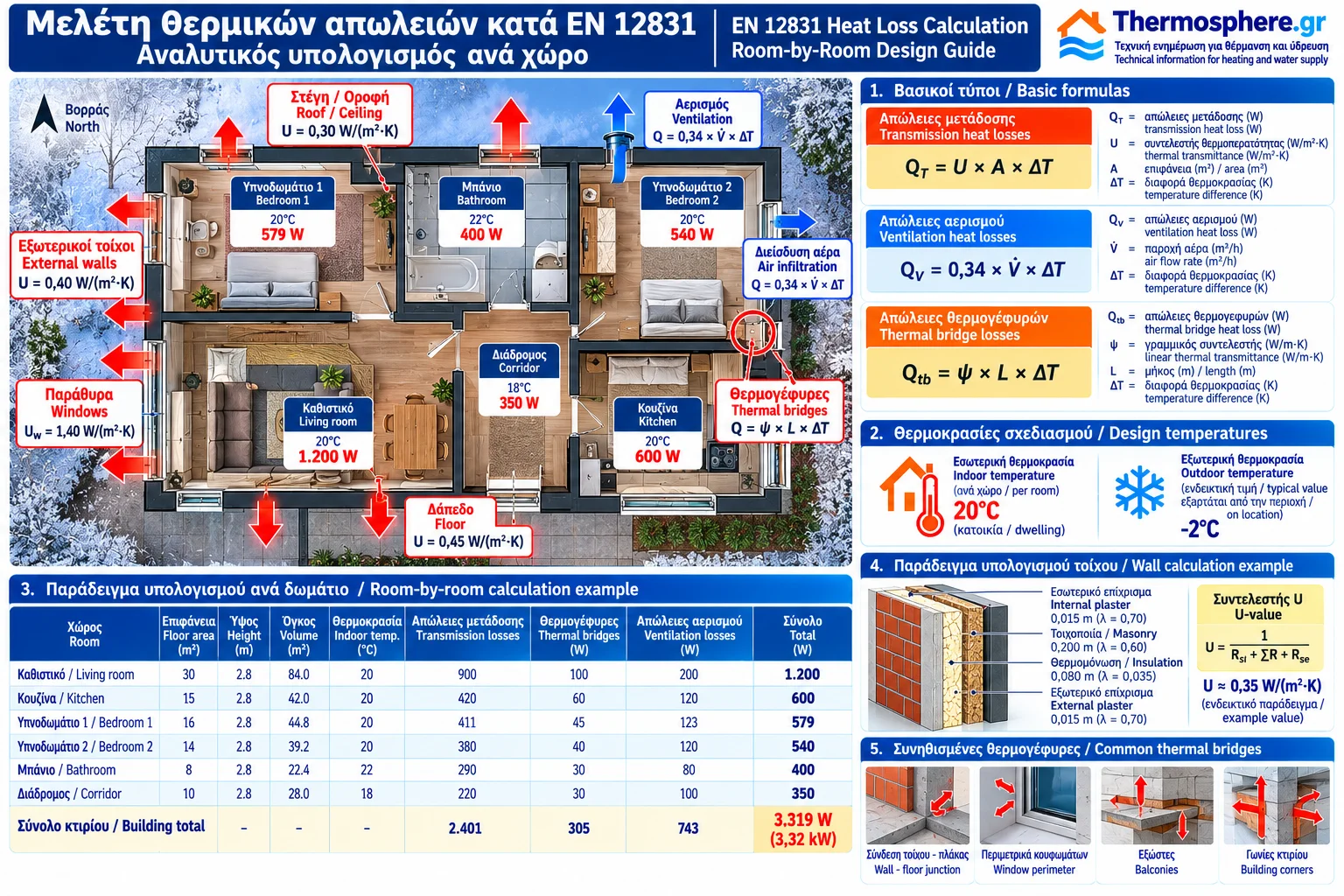
EN 12831 Heat Loss Calculation: Room-by-Room Design Guide
A building heat loss study is the foundation of proper heating system design. Its purpose is to determine the heating capacity required to maintain the desired indoor temperature in each room under specified winter design conditions.
A boiler, heat pump or radiator should not be selected solely on the basis of building floor area. Two rooms with identical floor areas can have substantially different heating loads depending on their external walls, windows, insulation, thermal bridges, ventilation and boundary conditions.
The European standard EN 12831-1 provides a methodology for calculating design heating loads.
This article explains the main calculation principles and presents a detailed educational example for a residential building.
Important: The worked examples are simplified and do not constitute a complete EN 12831-1 compliant design calculation. Actual engineering design requires the applicable edition of the standard, relevant national annex or national choices, appropriate climatic data and verified building information.
1. What Is a Building Heat Loss Study?
A heat loss study is the technical process used to determine the heating capacity required under design conditions.
Calculations are performed at two levels:
Room level: Determining the heating output required in each room.
Building level: Determining the overall design heating load used for selecting the heat source and designing the heating installation.
This distinction is essential.
For example, a dwelling may require a total of 8 kW, but that heating capacity is not distributed equally among all rooms.
A bedroom may require 800 W, while a large living room with more external glazing may require 2,500 W.
The building's total heating load is therefore insufficient for selecting individual radiators.
2. What Is EN 12831?
EN 12831-1, Energy performance of buildings — Method for calculation of the design heat load — Part 1: Space heating load, is a European standard for determining space heating design loads.
Its methodology considers building characteristics and specified design conditions.
Important parameters include:
Indoor design temperature.
Outdoor design temperature.
Building geometry.
Thermal transmittance of building elements.
Thermal bridges.
Conditions in adjacent spaces.
Ventilation and air infiltration.
Potential additional reheating requirements.
The standard is more comprehensive than a single heat loss equation.
Correct application requires appropriate classification of building elements, boundary conditions and airflow contributions.
3. Information Required Before Calculation
A reliable heat loss study requires accurate building information.
Geometric Data
Floor plans.
Room dimensions.
Ceiling heights.
External wall areas.
Window and door areas.
Roof and floor areas.
Thermal bridge geometry and lengths.
Construction Data
External wall construction.
Insulation layers.
Material thicknesses and properties.
Window specifications.
Roof construction.
Floor construction.
Airtightness information.
Operational Data
Room use.
Required indoor temperatures.
Ventilation requirements.
Heating schedules.
Conditions in adjacent heated and unheated spaces.
Climatic Data
Geographic location.
Outdoor design temperature.
Applicable national climatic data.
Missing or uncertain inputs increase calculation uncertainty.
4. Indoor Design Temperature
Indoor design temperature is the target temperature maintained under the specified heating design conditions.
It may vary between rooms.
For an educational example, assume:
Room | Assumed Design Temperature |
|---|---|
Living room | 20°C |
Bedroom | 20°C |
Kitchen | 20°C |
Bathroom | 22°C |
Corridor | 18°C |
These are assumptions for the example, not universal mandatory EN 12831 temperatures.
Actual design temperatures must follow project requirements and applicable national choices.
Heat transfer may also occur between adjacent rooms maintained at different temperatures.
5. Outdoor Design Temperature
Outdoor design temperature is the low external temperature used for determining the heating capacity required under design conditions.
It must not be selected arbitrarily.
It depends on geographic location and the applicable design methodology.
For example:
Indoor temperature = 20°C
Outdoor design temperature = −2°C
Temperature difference:
ΔT = 22 K
For a bathroom maintained at 22°C:
ΔT = 24 K
Different indoor design temperatures produce different temperature differences even within the same building.
6. Main Components of Design Heating Load
A simplified conceptual expression is:
Φdesign = ΦT + ΦV + Φadditional
Where:
ΦT = transmission heat loss.
ΦV = ventilation and infiltration heat loss, calculated without double-counting.
Φadditional = any additional capacity required by the applicable methodology, such as reheating capacity.
This is a conceptual summary rather than a complete reproduction of the standard's equations.
7. Transmission Heat Loss Calculation
For a simple element exposed to outdoor air:
ΦT = U × A × ΔT
Where:
U = thermal transmittance in W/(m²·K).
A = area in m².
ΔT = temperature difference in K.
ΦT = transmission heat loss in W.
Example:
External wall area = 15 m²
U-value = 0.40 W/(m²·K)
Temperature difference = 22 K
ΦT = 0.40 × 15 × 22
ΦT = 132 W
Each room requires separate consideration of the elements surrounding it.
8. Gross and Net Wall Areas
A common mistake is counting windows twice.
If an external wall has:
Gross area: 20 m².
Window area: 4 m².
The net opaque wall area is:
Awall = 20 − 4 = 16 m²
The wall is calculated using its U-value and the window using its Uw-value.
A consistent dimensional convention is particularly important when thermal bridges are also included.
9. Heat Loss to Unheated Spaces
Not every room adjoins outdoor air directly.
A heated room may adjoin:
An unheated staircase.
A storage room.
A garage.
An unheated basement.
An attic.
The temperature of the adjacent space is not necessarily equal to outdoor temperature.
Heat transfer must be assessed using an appropriate method, considering the thermal conditions and correction factors required by the calculation approach.
For a simple illustration:
Heated room = 20°C
Adjacent unheated storage room = 10°C
Temperature difference = 10 K rather than 22 K.
However, the storage room temperature must be established rather than assumed without justification.
10. Heat Loss to the Ground
Ground heat transfer requires specialised treatment.
It is generally incorrect to assume that the entire underside of a ground-contact floor is exposed directly to the outdoor air design temperature.
Relevant factors include:
Floor area.
Exposed perimeter.
Depth.
Floor thermal resistance.
Ground thermal properties.
Boundary conditions.
EN ISO 13370 provides relevant calculation methods.
Actual design studies must apply the appropriate method for ground floors and basements.
11. Thermal Bridges in Design Calculations
Thermal bridges can increase heat loss beyond the values calculated for planar building elements.
For a linear thermal bridge:
Φtb = ψ × L × ΔT
Where:
ψ = linear thermal transmittance.
L = thermal bridge length.
ΔT = temperature difference.
Example:
ψ = 0.10 W/(m·K)
L = 8 m
ΔT = 22 K
Φtb = 0.10 × 8 × 22
Φtb = 17.6 W
The ψ-value must match the actual construction detail and dimensional reference convention.
An arbitrary fixed percentage should not be added without checking compatibility with the calculation method.
12. Ventilation Heat Loss
Ventilation is essential for indoor air quality, but it creates a heating load when outdoor air is colder.
A simplified sensible ventilation heating load equation is:
ΦV ≈ 0.34 × V̇ × ΔT
Where:
V̇ = outdoor airflow in m³/h.
ΔT = temperature difference in K.
ΦV = heating load in W.
The factor 0.34 is approximate.
Example:
V̇ = 30 m³/h
ΔT = 22 K
ΦV ≈ 0.34 × 30 × 22
ΦV ≈ 224 W
Outdoor airflow must be determined using an appropriate method and the requirements of the space.
13. Ventilation and Air Infiltration
A heat loss study must distinguish between:
Controlled ventilation: Planned outdoor air supply.
Infiltration: Uncontrolled outdoor air entering through building envelope leakage paths.
These components are not always directly additive.
The airflow used in design calculations depends on the applicable method, ventilation arrangement and interaction between airflows.
Particular care is required for mechanical ventilation, heat recovery and buildings with measured airtightness values.
14. Room-by-Room Calculation Procedure
A practical calculation sequence is:
Step 1: Establish the indoor design temperature.
Step 2: Select the appropriate outdoor design temperature.
Step 3: Measure the building element areas.
Step 4: Determine thermal transmittance values.
Step 5: Calculate transmission heat losses.
Step 6: Include thermal bridge effects.
Step 7: Calculate ventilation and infiltration heat losses.
Step 8: Apply relevant corrections and additional requirements.
Step 9: Determine the room design heating load.
The procedure is repeated for every heated room.
15. Detailed Bedroom Calculation Example
Consider a hypothetical bedroom with:
Floor area: 16 m².
Ceiling height: 2.8 m.
Volume: 44.8 m³.
Indoor design temperature: 20°C.
Outdoor design temperature: −2°C.
Temperature difference:
ΔT = 22 K
For simplicity, the listed building elements are assumed to be directly exposed to outdoor air.
Building Element Heat Loss
Element | Area | U-Value | Heat Loss |
|---|---|---|---|
External walls, net area | 18 m² | 0.45 | 178.2 W |
Window | 3 m² | 1.40 | 92.4 W |
Roof | 16 m² | 0.30 | 105.6 W |
Total:
ΦT = 376.2 W
For this example, the floor is assumed to adjoin another room maintained at the same temperature, producing no net heat transfer under the specified assumptions.
Thermal Bridges
Assumed additional thermal bridge heat loss:
Φtb = 35 W
Ventilation
Assumed total effective outdoor airflow:
V̇ = 22.4 m³/h
ΦV ≈ 0.34 × 22.4 × 22
ΦV ≈ 167.6 W
Total Room Heating Load
Φ = 376.2 + 35 + 167.6
Φ ≈ 579 W
The simplified heating load is approximately:
0.58 kW
No additional reheating capacity has been included.
The assumed airflow and thermal bridge losses are illustrative inputs rather than outputs of a full regulatory calculation.
16. Residential Building Calculation Example
Consider a hypothetical dwelling with five heated rooms.
The following table presents illustrative heating loads to demonstrate how room-by-room results can be summarised.
Room | Floor Area | Transmission and Thermal Bridges | Ventilation | Total |
|---|---|---|---|---|
Living room | 30 m² | 900 W | 300 W | 1,200 W |
Kitchen | 15 m² | 420 W | 180 W | 600 W |
Bedroom 1 | 16 m² | 411 W | 168 W | 579 W |
Bedroom 2 | 14 m² | 380 W | 160 W | 540 W |
Bathroom | 8 m² | 290 W | 110 W | 400 W |
Total | 83 m² | 2,401 W | 918 W | 3,319 W |
The simplified total heating load is:
3.319 kW
This does not mean a heat source should automatically be selected with a nominal capacity of exactly 3.319 kW.
Actual operating conditions, equipment capacity at design conditions and any additional requirements must be evaluated.
The table is educational and does not represent a complete regulatory design study.
17. Why Room-by-Room Calculations Matter
Consider two rooms with identical floor areas of 15 m².
The first has:
One external wall.
A small window.
Good insulation.
The second has:
Two external walls.
Large windows.
More thermal bridges.
Although their floor areas are identical, the second room may have substantially higher heat loss.
Selecting identical radiators based only on floor area can therefore result in an incorrect distribution of heating output.
Room-by-room calculations support more accurate selection of heating emitters.
18. Room Heating Load vs Building Heating Load
Summing individual room heating loads requires care.
Heat transfer between heated rooms may affect individual room loads but does not necessarily represent a net loss from the entire building.
Furthermore, the applicable methodology may treat certain ventilation contributions and additional heating capacities differently at building level.
The overall design heating load should therefore follow the relevant calculation procedure rather than simply adding every potential allowance without checking its applicability.
19. Additional Reheating Capacity
Some buildings operate with reduced indoor temperatures during certain periods.
For example, the temperature may be lowered overnight or during periods of non-occupancy.
When normal heating resumes, additional capacity may be needed to restore indoor temperatures within a specified period.
This depends on:
Building thermal mass.
Setback duration.
Temperature reduction.
Required reheating time.
Operating strategy.
Additional reheating capacity should be calculated using an appropriate method, not added as an arbitrary percentage.
20. Connection to Radiator Sizing
Each room's heating load determines the required heating output of its emitters.
However, radiator output depends on supply water temperature, return water temperature and room temperature.
A radiator rated at a particular output under high-temperature conditions may deliver substantially less heat in a low-temperature system.
Therefore, knowing the room heating load is not enough.
The radiator's actual output under the intended operating conditions must also be evaluated.
21. Connection to Heat Pump Sizing
Accurate heat load calculations are especially important for heat pump selection.
Available heat pump capacity can vary with:
Outdoor air temperature.
Heating water supply temperature.
Heat pump type.
Defrost conditions.
Compressor operating characteristics.
Selection should be based on the actual available heating capacity under the required design conditions.
A nominal rating at one standard test condition is not sufficient by itself.
22. Connection to Boiler Sizing
Design heating load is a fundamental input for boiler selection.
Other considerations include:
Modulation range.
Minimum heating output.
Part-load operation.
Domestic hot water requirements, where applicable.
Hydraulic configuration.
Excessive boiler capacity may increase cycling, particularly when the minimum boiler output frequently exceeds the building's heating demand.
23. Common Heat Loss Study Mistakes
Using Only W/m² Estimates
Generic area-based rules cannot replace detailed room calculations.
Incorrect Outdoor Design Temperature
This can significantly affect results.
Ignoring Windows
Window U-values often differ considerably from wall U-values.
Double-Counting Areas
Gross wall area should not be combined carelessly with additional full window areas.
Ignoring Thermal Bridges
This can underestimate transmission heat loss.
Arbitrary Ventilation Rates
Outdoor airflow should be established using an appropriate method.
Double-Counting Ventilation and Infiltration
This can overestimate heating demand.
Incorrect Treatment of Unheated Spaces
Not all adjacent spaces should be assumed to be at outdoor design temperature.
Arbitrary Safety Factors
These may result in oversized heating equipment.
24. Heat Loss Study vs Energy Performance Assessment
A design heat loss study primarily determines heating capacity required under specified design conditions.
An energy performance assessment examines building behaviour over a longer period and considers additional factors, including:
Seasonal climate variation.
Solar gains.
Internal heat gains.
Operating schedules.
System efficiencies.
Energy consumption.
A building with a 6 kW design heating load does not continuously require 6 kW throughout the entire heating season.
25. Relevant Standards
Important technical references include:
EN 12831-1: Design heating load calculation for space heating.
EN ISO 6946: Thermal resistance and thermal transmittance of building components.
EN ISO 10077: Thermal performance of windows and doors.
EN ISO 10211: Detailed thermal bridge calculations.
EN ISO 14683: Simplified linear thermal bridge assessment.
EN ISO 13370: Heat transfer through the ground.
EN ISO 9972: Building airtightness measurements.
For projects in Greece, applicable KENAK requirements, relevant TOTEE technical guidance and national choices must also be considered.
Conclusion
A building heat loss study is not simply a multiplication of floor area by a generic W/m² figure.
It is a technical calculation process that examines the actual heating requirements of individual spaces.
Room-by-room design calculations support appropriate radiator selection and more accurate sizing of the overall heating system.
EN 12831-1 provides the methodological framework for design heating load calculations, while correct application depends on reliable building data and appropriate engineering assessment.
Good heating design starts with calculating the heating requirements of each room — not with selecting the equipment.
This article is intended for technical information. Numerical examples are educational and do not replace a complete engineering design study.
Thermosphere.gr — Technical information for heating and water supply.