
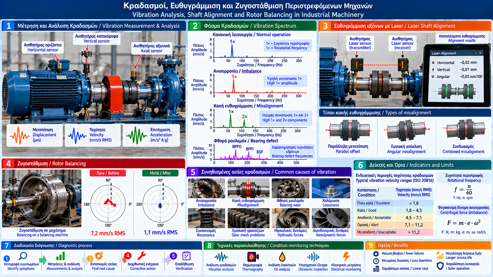
# Vibration Analysis, Shaft Alignment and Rotor Balancing in Industrial Machinery
## Introduction
Rotating machinery is essential to industrial operations. Pumps, electric motors, fans, compressors, gearboxes and turbomachinery operate under dynamic loads that generate mechanical vibration.
Vibration is not always evidence of a fault. Every rotating machine exhibits some vibration during normal operation.
However, increasing vibration or changes in its characteristics may indicate imbalance, misalignment, bearing damage, mechanical looseness or other problems.
Reliable diagnosis requires measurements, frequency analysis and assessment of actual operating conditions.
## 1. What Is Mechanical Vibration?
Mechanical vibration is the oscillatory movement of a component or machine around an equilibrium position.
It is characterized by:
- Frequency.
- Amplitude.
- Phase.
- Direction.
- Time variation.
In rotating equipment, excitation may be associated with shaft rotation, bearing forces, gear meshing and hydraulic or aerodynamic forces.
## 2. How Is Vibration Measured?
The main measured quantities are:
### Displacement
Describes changes in the position of a point.
Typical units: μm or mm.
### Vibration Velocity
Describes the rate of change of displacement.
Typical unit: mm/s.
Root mean square velocity, or RMS, is commonly used for overall vibration evaluation in suitable machine categories.
### Acceleration
Describes the rate of change of velocity.
Typical units: m/s² or g.
Acceleration is often used for higher-frequency analysis and bearing fault detection.
The most suitable parameter depends on the machine, frequency range and diagnostic method.
## 3. Rotational Frequency and Vibration Spectrum
Rotational frequency is calculated as:
f = n / 60
where:
f = rotational frequency in Hz.
n = rotational speed in rpm.
Example:
For a motor operating at 1,500 rpm:
f = 1,500 / 60 = 25 Hz.
This is called the 1× rotational frequency.
Vibration spectra may contain:
- 1× rotational frequency.
- 2× rotational frequency.
- Higher harmonics.
- Bearing defect frequencies.
- Gear mesh frequencies.
A frequency component is a diagnostic clue, not definitive proof of a particular fault.
## 4. Rotor Imbalance
Imbalance occurs when a rotating body's mass distribution produces unbalanced centrifugal forces.
Potential causes include:
- Uneven material distribution.
- Deposits on impellers.
- Material loss.
- Wear.
- Incorrect assembly.
- Component deformation.
A common indicator is elevated 1× vibration, especially in the radial direction.
However, other faults can also produce strong 1× vibration.
Additional information, including phase and response to speed changes, may be necessary.
## 5. What Is Rotor Balancing?
Balancing corrects the mass distribution of a rotating body to reduce unbalanced forces and moments.
It may be performed:
- On a dedicated balancing machine.
- In situ using suitable instruments.
- In one correction plane.
- In two or more correction planes, depending on the rotor.
Method selection depends on geometry, dynamic behavior and equipment requirements.
## 6. Static and Dynamic Imbalance
### Static Imbalance
The center of mass does not coincide with the rotational axis.
In suitable cases, it can be corrected in one plane.
### Couple Imbalance
Mass distribution creates an unbalanced moment even when the overall center of mass lies on the rotational axis.
### Dynamic Imbalance
Involves a general distribution of unbalanced forces and moments.
It often requires correction in two planes.
The balancing approach depends not only on rotor size but also on dynamic behavior.
## 7. Example of Imbalance Force
For a simplified concentrated imbalance:
F = m × e × ω²
where:
F = centrifugal force in N.
m = imbalance mass in kg.
e = eccentricity in m.
ω = angular velocity in rad/s.
Assume:
m = 0.02 kg.
e = 0.10 m.
n = 1,500 rpm.
Angular velocity:
ω = 2π × 1,500 / 60 ≈ 157.1 rad/s.
Therefore:
F ≈ 0.02 × 0.10 × 157.1².
F ≈ 49.3 N.
Even a small imbalance can generate a substantial periodic force.
Actual vibration response also depends on system mass, stiffness, damping and natural frequencies.
## 8. Shaft Misalignment
Misalignment occurs when the shafts of connected machines do not have the intended relative position.
Main types:
- Parallel offset.
- Angular misalignment.
- Combined misalignment.
Possible consequences:
- Increased vibration.
- Coupling stress.
- Bearing wear.
- Higher temperatures.
- Seal leakage.
- Reduced reliability.
Misalignment may generate 1×, 2× or other vibration components, but no single spectral feature proves misalignment in every case.
## 9. Laser Shaft Alignment
Laser alignment systems accurately determine the relative positions of connected shafts.
The procedure generally includes:
1. Checking foundation and mounting.
2. Checking soft foot.
3. Inspecting coupling condition.
4. Installing measurement sensors.
5. Rotating shafts according to instrument instructions.
6. Calculating corrections.
7. Moving equipment and adjusting supports.
8. Repeating measurements.
9. Verifying final alignment.
Acceptable tolerances depend on rotational speed, coupling type and manufacturer requirements.
## 10. What Is Soft Foot?
Soft foot occurs when machine feet do not contact the base correctly.
Tightening the mounting bolts may distort the machine frame.
This can affect:
- Alignment.
- Bearing loading.
- Vibration.
- Measurement repeatability.
Soft foot should be corrected before final alignment.
## 11. Thermal Growth and Alignment
Operating temperature can change relative shaft positions.
Equipment aligned correctly when cold may behave differently during operation.
Critical applications may require consideration of:
- Thermal growth.
- Temperature differences.
- Load changes.
- Piping movement.
- Thermal compensation specifications.
Any required cold alignment offsets must be based on engineering data rather than arbitrary assumptions.
## 12. Mechanical Looseness
Mechanical looseness may result from:
- Loose bolts.
- Damaged foundations.
- Excessive clearances.
- Support failures.
- Incorrect assembly.
Vibration spectra may show multiple harmonics and nonlinear behavior.
Confirmation requires inspection and correlation with measured data.
## 13. Resonance and Natural Frequencies
Every mechanical system has natural frequencies.
When excitation frequency approaches a natural frequency, vibration may increase significantly.
This is called resonance.
Potential causes include:
- Changes in rotational speed.
- Changes in stiffness.
- Inadequate foundations.
- Changes in mass.
- Deteriorated supports.
Corrective action may involve changing excitation frequency, stiffness, mass or damping after suitable engineering assessment.
Balancing alone does not necessarily solve resonance.
## 14. Bearing-Related Vibration
Rolling-element bearing defects can produce characteristic frequencies associated with:
- Outer race.
- Inner race.
- Rolling elements.
- Cage.
These frequencies depend on bearing geometry and rotational speed.
High-frequency techniques and envelope analysis are often used to identify developing defects.
Assessment should be combined with operating history and machine condition.
## 15. Vibration Sensor Locations
Sensors should be installed at suitable locations near bearings and primary vibration transmission paths.
Common measurement directions include:
- Horizontal.
- Vertical.
- Axial.
Consistent measurement locations are essential for reliable trending.
Measurements taken at different locations or operating conditions may not be directly comparable.
## 16. Vibration Evaluation Standards
The ISO 20816 series addresses machine vibration evaluation, with different parts and criteria for different equipment categories.
The ISO 21940 series addresses rotor balancing and related requirements.
Selecting the applicable standard requires consideration of:
- Machine type.
- Rated power.
- Rotational speed.
- Bearing arrangement.
- Operating conditions.
- Manufacturer specifications.
There is no single universal vibration limit for all industrial machines.
## 17. Industrial Fan Troubleshooting Example
An industrial fan develops increasing vibration.
Investigation includes:
1. Recording speed and load.
2. Measuring vibration near bearings.
3. Comparing historical data.
4. Analyzing spectrum and phase.
5. Checking impeller deposits.
6. Inspecting foundations.
7. Checking alignment.
8. Evaluating potential imbalance.
If deposits are confirmed as the cause of imbalance, they should first be removed using a safe procedure.
Balancing is then performed if still required.
## 18. Common Diagnostic Mistakes
Common mistakes include:
- Balancing without identifying the cause.
- Ignoring soft foot.
- Aligning without checking pipe strain.
- Comparing readings at different speeds.
- Using unsuitable sensors.
- Overlooking resonance.
- Treating one spectral feature as definitive proof.
- Ignoring manufacturer limits.
Diagnosis should rely on multiple lines of evidence.
## 19. Preventive and Predictive Monitoring
A monitoring program may include:
- Establishing baseline vibration levels.
- Periodic measurements.
- Continuous monitoring of critical machines.
- Trend analysis.
- Bearing temperature monitoring.
- Maintenance history records.
- Post-repair verification.
Alarm and shutdown thresholds should be based on equipment specifications, standards, historical data and risk assessment.
## 20. Safety During Alignment and Balancing
Alignment and balancing require strict safety procedures.
Before mechanical intervention:
- Isolate equipment safely.
- Verify the absence of hazardous energy.
- Apply lockout/tagout where required.
- Prevent unintended rotation.
- Check protective guards.
- Follow an approved restart procedure.
Measurements on running equipment and balancing trials should only be performed by trained personnel using approved methods and appropriate protective measures.
## Conclusion
Vibration provides valuable information about the condition of industrial rotating machinery.
Imbalance, misalignment, looseness, bearing damage and resonance may produce similar symptoms.
Reliable diagnosis requires frequency analysis, phase measurements where needed, accurate alignment and technically justified balancing.
Systematic condition monitoring reduces recurring failures and supports improved equipment reliability and service life.
Thermosphere.gr – Technical Knowledge for Professionals.