
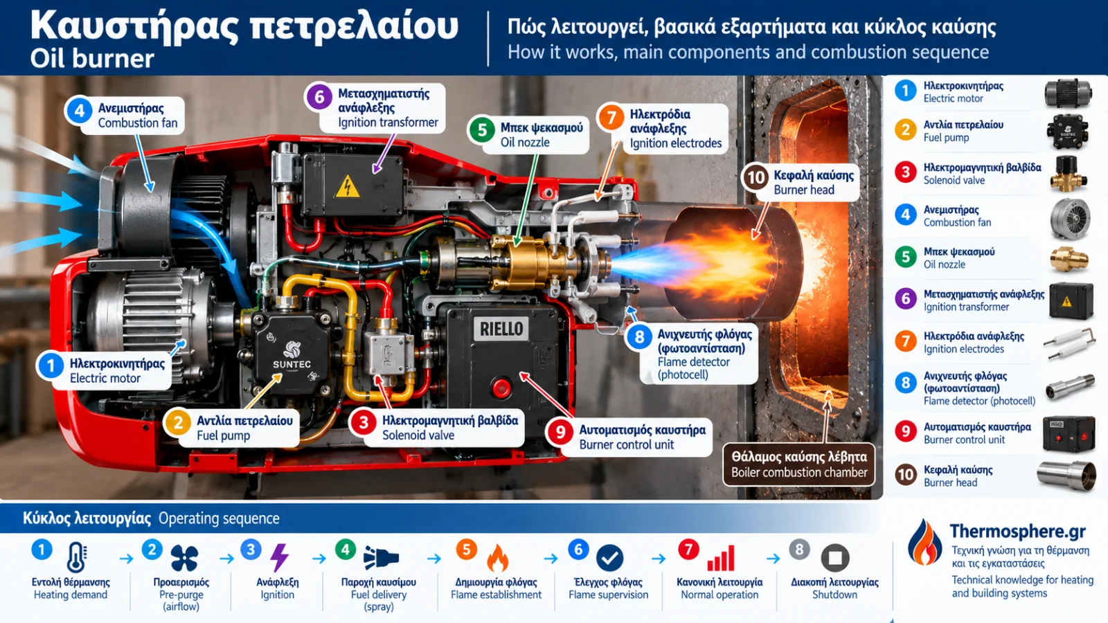
Oil Burner Operation: How It Works, Main Components and Combustion Sequence
An oil burner is an essential component of many central heating installations. Its purpose is to deliver properly prepared fuel and combustion air to a compatible combustion chamber, establish a controlled flame and safely stop fuel delivery when the required operating conditions are not met.
Although an oil burner may appear relatively simple from the outside, its operation depends on several interconnected mechanical, electrical and electronic components.
The fuel pump, nozzle, combustion fan, ignition electrodes, flame detector and burner safety control perform distinct but closely coordinated functions.
Understanding these components helps explain normal burner operation and identify symptoms that may indicate a fault.
This Thermosphere.gr technical guide examines the basic principles of a pressure-atomising forced-draught oil burner, its main components and the typical ignition and combustion sequence.
1. What Is an Oil Burner?
An oil burner is a device that prepares and burns liquid fuel inside a suitable combustion chamber.
Many oil-fired heating installations use pressure-atomising burners equipped with combustion-air fans.
Fuel is delivered to a nozzle under pressure, atomised into fine droplets and mixed with combustion air.
Ignition is provided by a high-voltage ignition system, while an automatic burner control supervises flame establishment and operation.
The heat generated by combustion is transferred through the boiler's heat-exchange surfaces to the heating water.
The burner and boiler are separate components, even though they operate together as an integrated heating appliance.
2. Main Components of an Oil Burner
A typical pressure-atomising oil burner contains several essential components.
Component | Main function |
|---|---|
Electric motor | Drives the combustion fan and, in many designs, the oil pump |
Combustion fan | Supplies combustion air |
Fuel pump | Delivers oil at the required pressure |
Oil nozzle | Atomises fuel and establishes the spray pattern |
Ignition electrodes | Produce the ignition spark |
Ignition transformer or electronic igniter | Generates high voltage |
Flame detector | Monitors flame presence |
Solenoid valve | Controls fuel delivery to the nozzle |
Burner control unit | Coordinates startup, operation and safety functions |
Burner head | Helps establish the combustion-air pattern and flame stability |
The precise arrangement depends on the burner manufacturer, model and operating principle.
3. How Does the Oil Burner Pump Work?
The oil pump delivers fuel to the nozzle at the pressure required by the burner design.
Many domestic burners use gear-type pumps driven by the burner motor.
Depending on the model, the pump may include:
A suction connection.
A return connection where required.
A pressure-regulating mechanism.
A pressure measurement port.
An internal filter.
An integrated or associated fuel solenoid valve.
Operating pressure must be selected according to the burner manufacturer's instructions and the nozzle specifications.
There is no single correct pump pressure for every oil burner.
The pump's performance also depends on the fuel supply arrangement, suction conditions and fuel properties.
4. What Is an Oil Burner Nozzle?
The oil nozzle is responsible for atomising the fuel inside the combustion chamber.
As pressurised oil passes through the nozzle, it forms a spray of small droplets that facilitates mixing with combustion air.
Oil nozzles are generally specified by:
Nominal flow rate.
Spray angle.
Spray pattern.
Manufacturer-defined operating characteristics.
Many nozzles display a nominal flow rate in US gallons per hour, abbreviated as US gal/h or GPH, under specified test conditions.
Actual fuel flow changes with pressure and fuel properties.
Nozzle selection must consider more than the required heat input. Burner-head characteristics, combustion-chamber geometry and manufacturer requirements are also important.
5. What Does the Combustion Fan Do?
The combustion fan provides the air needed to burn the fuel.
In forced-draught oil burners, airflow and air distribution influence:
Fuel-air mixing.
Flame stability.
Residual oxygen in the flue gases.
Soot formation.
Carbon monoxide emissions.
Overall combustion quality.
Insufficient air can contribute to incomplete combustion, soot formation and elevated carbon monoxide emissions.
Excessive air may increase flue-gas heat losses and affect flame stability.
Correct adjustment must be confirmed by a qualified technician using appropriate combustion-analysis instruments.
Visual flame appearance alone is not a reliable indication of correct combustion.
6. How Do Ignition Electrodes Work?
Ignition electrodes produce a high-voltage electrical spark near the fuel spray.
The voltage is generated by an ignition transformer or electronic ignition unit.
The spark ignites the appropriately prepared fuel-air mixture.
Correct electrode positioning is essential.
Incorrect electrode spacing or alignment can lead to unreliable ignition.
However, electrode dimensions and positions vary between burner models.
The manufacturer's specified measurements and procedures must always be followed.
Safety warning: Ignition systems generate hazardous high voltage. Inspection and adjustment must only be performed by appropriately qualified technicians.
7. What Is a Flame Detector?
The flame detector is a critical burner safety component.
Many oil burners use a light-sensitive resistor, often called a photocell or LDR, to detect light emitted by the flame.
Other burners may use different flame-detection technologies.
The detector provides the burner control unit with information about whether a flame is present.
If the expected flame is not established within the permitted safety period, or if the flame disappears during operation, the control unit must respond according to its approved safety sequence.
The exact response depends on the control model and burner configuration.
Bypassing or artificially activating a flame detector is dangerous and is not an acceptable operating or repair procedure.
8. What Does the Burner Control Unit Do?
The burner control unit coordinates the burner's operating stages and safety functions.
Depending on its design, it may control:
The startup sequence.
Flame supervision.
The burner motor and fan.
The ignition system.
The fuel solenoid valve.
Safety timing.
Shutdown and lockout conditions.
Different burner controls use different operating sequences.
Pre-purge, ignition and flame-supervision timing may vary between models.
These safety parameters must never be modified arbitrarily.
9. The Oil Burner Startup Sequence
A typical forced-draught oil burner follows a sequence of coordinated stages.
Stage 1: Heating Demand
A thermostat or boiler controller generates a request for heat.
Provided that the relevant operating limits and safety conditions permit operation, the burner controller begins its startup procedure.
Stage 2: Motor Start and Airflow
The motor starts and the combustion fan supplies air.
Where the burner design includes a defined pre-purge period, this takes place according to the controller's programmed sequence.
Stage 3: Ignition Activation
The ignition unit produces a spark.
The timing and duration depend on the burner control system.
Stage 4: Fuel Delivery
The fuel solenoid valve opens when permitted by the burner controller.
Oil is atomised through the nozzle and ignites when the necessary conditions are present.
Stage 5: Flame Confirmation
The flame detector confirms that combustion has been established.
If the required flame is not detected within the specified safety time, the controller interrupts fuel delivery and follows its approved fault procedure.
Stage 6: Normal Operation
The burner continues operating while heating demand remains valid and all required safety conditions are satisfied.
Stage 7: Shutdown
When heating demand ends or an operating limit requires shutdown, fuel delivery stops.
Any additional ventilation or shutdown functions depend on the burner model.
Important: This is a general description. The actual component activation sequence is determined by the specific burner control unit.
10. Single-Stage, Two-Stage and Modulating Oil Burners
Oil burners are available with different heat-output control capabilities.
Single-Stage Burners
A single-stage burner operates at one designated firing rate when heating is requested.
Its heat input depends on the approved fuel and air settings.
Two-Stage Burners
A two-stage burner provides two operating levels, typically a lower and a higher firing rate.
Transitions between stages are controlled according to the burner design.
Progressive or Modulating Burners
Larger or specialised installations may use burners capable of adjusting output over a wider operating range.
The available modulation range and control method depend on the specific equipment.
11. How Do the Burner and Boiler Work Together?
The burner produces the flame, while the boiler transfers combustion heat to the heating water.
Correct integration requires compatibility between:
Burner heat input.
Combustion chamber characteristics.
Boiler combustion-side resistance.
Flame geometry.
Flue and chimney requirements.
Control and safety systems.
A burner is not automatically suitable for a boiler simply because it can be physically attached to the boiler door.
Selection must follow manufacturer specifications and approved operating ranges.
12. Why Is Combustion Quality Important?
Proper combustion requires suitable fuel-air mixing, effective atomisation and a stable flame.
Combustion assessment may include measurements of:
Oxygen concentration (O₂).
Carbon dioxide concentration (CO₂), measured or calculated where applicable.
Carbon monoxide (CO).
Flue-gas temperature.
Smoke or soot index.
Flue draught or pressure where required.
Measurements must be performed using suitable instruments and interpreted according to the equipment's technical requirements.
A visually acceptable flame does not establish that combustion is safe or efficient.
13. What Is Oil Burner Lockout?
Lockout is a safety condition in which the burner control stops operation following a defined fault.
Depending on the equipment, possible causes include:
Failure to establish a flame.
Flame loss during operation.
An unexpected flame signal.
A component or operating-sequence fault.
Some burner controls provide a fault indicator or diagnostic code.
Repeated resets without identifying the cause should be avoided. Repeated startup attempts may create hazardous conditions.
A burner that repeatedly locks out requires inspection by a qualified technician.
14. Why Does Fuel Quality Matter?
Fuel quality affects pump operation, nozzle performance and combustion stability.
Problems may result from:
Water contamination.
Sediment and particles.
Blocked filters.
Unsuitable storage conditions.
Changes in fuel properties.
Proper fuel-tank and supply-system maintenance supports reliable operation.
The fuel must meet the applicable specifications required by the equipment manufacturer and relevant regulations.
15. Signs of Abnormal Oil Burner Operation
Potential warning signs include:
Repeated burner lockout.
Difficulty starting.
Unusual operating noise.
Fuel odours.
Visible oil leakage.
Smoke or excessive soot.
Unstable operation.
Unexpected increases in fuel consumption.
These symptoms do not, by themselves, identify the defective component.
If flue gases enter the occupied space, carbon monoxide is suspected, smoke is present indoors or fuel is leaking, the heating equipment should not continue operating until the situation has been made safe and professionally assessed.
16. What Should the Property Owner Check?
Property owners can monitor basic operating conditions without interfering with the burner.
Useful observations include:
Whether a fault indication is displayed.
Whether the room thermostat is requesting heat.
Whether sufficient fuel is available.
Whether visible leakage is present.
Whether unusual noises or odours occur.
Whether scheduled maintenance has been completed.
Owners should not attempt to adjust fuel-pump pressure, replace nozzles, reposition ignition electrodes or bypass safety devices.
These tasks require a qualified technician and, where applicable, combustion testing.
17. Frequently Asked Questions
What Is the Difference Between an Oil Burner and an Oil Boiler?
The burner prepares and burns the fuel. The boiler transfers the resulting heat to the heating water.
What Does the Oil Pump Do?
It supplies fuel to the nozzle at the required pressure according to the system specifications.
What Does the Nozzle Do?
It atomises oil into small droplets and creates the fuel spray inside the combustion chamber.
What Does the Photocell Do?
In compatible burner systems, it detects flame light and provides information to the safety control.
Why Does an Oil Burner Lock Out?
The control unit may stop operation when a required safe condition is not confirmed, such as during ignition failure or flame loss.
Can I Replace the Oil Nozzle Myself?
Nozzle selection and replacement directly affect combustion performance and should be performed by a qualified technician, followed by the required checks.
Do All Oil Burners Have the Same Startup Sequence?
No. Operating sequences and safety timing depend on the burner control unit and the burner design.
Conclusion
An oil burner is an integrated combustion system in which fuel delivery, atomisation, combustion airflow, ignition and flame supervision must work together.
Reliable operation does not depend on a single component but on the correct coordination of the entire mechanical and electronic system.
Safe and efficient operation requires a burner correctly matched to the boiler, appropriate installation, reliable safety controls and properly documented combustion testing.
The following Thermosphere.gr articles will examine oil burner adjustment, troubleshooting, maintenance and fuel consumption in greater detail.
Technical References and Further Reading
EN 267: Automatic forced draught burners for liquid fuels.
EN 230: Automatic burner control systems for oil burners.
EN 298: Automatic burner control systems for burners and appliances burning gaseous or liquid fuels.
Riello: Official oil burner documentation — https://www.riello.com/
Baltur: Official burner technical documentation — https://www.baltur.com/
Danfoss: Oil pump and nozzle technical documentation — https://www.danfoss.com/
These references provide general technical background. Actual adjustments and interventions require the official installation and service documentation for the exact burner model.
Safety note: This article provides general technical information. Work involving burners, fuel systems, ignition circuits and safety devices must only be performed by appropriately qualified technicians.
Thermosphere.gr — Technical knowledge for heating and building systems.