
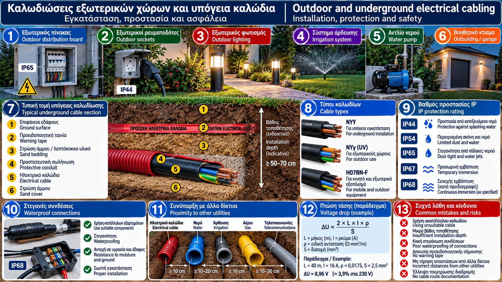
Outdoor Electrical Wiring and Underground Cables: Complete Guide to Installation, Protection and Safety
Outdoor electrical wiring represents a specialized category of electrical installations because it operates under conditions significantly different from those found inside buildings.
Rain, moisture, solar radiation, temperature variations, mechanical stress and ground excavation work can affect the safety and service life of an electrical circuit.
Underground wiring is commonly used to supply outdoor lighting, water pumps, auxiliary buildings, garden distribution boards and other permanently installed equipment.
Proper installation involves more than selecting a cable suitable for outdoor use. It also requires appropriate cable routing, mechanical protection, moisture management, reliable connections, correct electrical protection and final verification.
This guide examines the fundamental technical requirements for outdoor and underground electrical wiring, common installation mistakes and the principles of safe electrical design.
1. What Is Outdoor Electrical Wiring?
Outdoor electrical wiring refers to electrical circuits installed outside the protected interior areas of a building.
These circuits may supply:
Garden lighting.
Outdoor socket outlets.
Water pumps.
Irrigation systems.
Auxiliary installations.
Storage buildings and detached structures.
Outdoor electrical distribution boards.
Permanently installed electromechanical equipment.
Exposure to environmental conditions makes it essential to select materials and installation methods suitable for the specific application.
2. Why Does Outdoor Wiring Require Special Protection?
Operating conditions affect both electrical cables and other installation components.
External Influence | Possible Risk |
Rain and moisture | Water ingress and insulation deterioration |
Solar radiation | Aging of unsuitable materials |
High temperatures | Increased thermal stress |
Low temperatures | Reduced flexibility of certain materials |
Mechanical stress | Crushing or penetration |
Chemical substances | Sheath deterioration |
Excavation work | Accidental cable damage |
Flooding | Exposure of connections and equipment to water |
Protection must be designed according to actual environmental conditions rather than relying solely on the general description of an “outdoor installation.”
3. Selecting Suitable Electrical Cables
Not all electrical cables are suitable for outdoor or underground installation.
Selection must be based on the manufacturer’s declared product characteristics and applicable standards.
Main Selection Criteria
Rated voltage.
Conductor material.
Conductor cross-sectional area.
Insulation type.
Outer sheath.
Moisture resistance.
Ultraviolet radiation resistance.
Temperature limits.
Mechanical strength.
Suitability for direct burial, where applicable.
Important Distinction
A cable suitable for outdoor use is not automatically suitable for direct burial in the ground.
Direct-burial suitability must be supported by the product specifications and the installation requirements.
4. Underground Cables: Fundamental Design Principles
An underground electrical circuit must be designed before excavation begins.
What Should Be Established During Design?
Supply point.
Circuit destination.
Electrical load.
Cable route length.
Cable type.
Protection method.
Ground conditions.
Proximity to other underground utilities.
Maintenance requirements.
Protection against electric shock and overcurrent.
The design should also account for future work in the area.
5. Choosing an Underground Cable Route
The underground route should be selected to minimize the risk of mechanical damage.
Basic Principles
Avoid unnecessary changes in direction.
Minimize routes through areas where excavation is likely.
Provide suitable protection at crossings with other utility networks.
Design appropriate penetrations through foundations and walls.
Record the actual cable route.
Provide access to necessary maintenance points.
Why Is Documentation Important?
An underground electrical circuit is no longer visible after installation is completed.
Missing drawings can significantly increase the risk of cable damage during future work.
6. Underground Cable Burial Depth
Installation depth is an important factor in the mechanical protection of underground cables.
However, there is no single burial depth suitable for every installation.
The required depth depends on:
Applicable regulatory requirements.
Operating voltage.
Cable type.
Installation method.
Likelihood of mechanical stress.
Vehicle traffic.
Ground conditions.
Project-specific requirements.
What Applies in Practice?
The final installation depth must be established by the approved design and relevant requirements.
Choosing an arbitrary burial depth without assessing the risks is not appropriate engineering practice.
7. Underground Conduits and Mechanical Protection
In many applications, underground cables are installed inside suitable protective conduits.
Conduits can provide:
Protection against certain mechanical stresses.
Organized cable routing.
Protection at crossings and penetrations.
Potential for future cable replacement, provided the system has been designed accordingly.
Selection Criteria
Compression resistance.
Impact resistance.
Suitability for underground installation.
Internal diameter.
Compatibility with the cable.
Moisture conditions.
Installation requirements.
Important Consideration
The presence of a conduit does not eliminate every risk.
Some conduit systems may accumulate water because of condensation or moisture ingress.
The cable must therefore be suitable for the actual environmental conditions.
8. Ground Layers, Bedding and Warning Markers
The construction of an underground cable route may include suitable bedding materials, protective elements and warning markers.
Purpose of Bedding
Appropriate material surrounding the cable route can reduce the risk of localized mechanical stress caused by sharp objects in the ground.
Warning Markers
Where required, suitable warning tapes or other identification systems are installed.
Their purpose is to alert personnel carrying out future excavation work.
Technical Consideration
Layer composition, separation distances and marker positions must follow the project requirements and relevant specifications.
A generic trench detail should not be copied indiscriminately into every installation.
9. Direct Burial or Installation Inside a Conduit?
These two installation methods have different characteristics.
Criterion | Direct Burial | Conduit Installation |
Cable type | Must be suitable for direct burial | Must be suitable for conduit conditions |
Mechanical protection | Depends on cable construction and installation | Enhanced by a suitable conduit |
Replacement | Usually more difficult | May be easier |
Thermal behavior | Influenced by ground conditions | Influenced by conduit and ground conditions |
Cost | Depends on the application | Includes additional materials |
Conduit installation is not always the best solution, and direct burial is not suitable for every cable.
The final choice must follow a technical assessment.
10. Thermal Behavior of Underground Cables
The current-carrying capacity of an underground cable depends on how effectively heat is dissipated into the surrounding environment.
Important factors include:
Ground temperature.
Soil thermal resistivity.
Burial depth.
Cable grouping.
Conduit installation.
Load current.
Cable construction.
Why Does Soil Thermal Resistivity Matter?
Ground conditions do not provide identical heat dissipation in every location.
Soil composition, moisture content and compaction can affect thermal performance.
Example
Two identical cables carrying the same current may operate at different temperatures if installed under different ground conditions.
Consequently, cable sizing must not be based exclusively on nominal conductor cross-sectional area.
11. Voltage Drop Along Long Underground Cable Routes
Outdoor and underground electrical circuits may extend over considerable distances.
This makes voltage drop an essential design consideration.
For a simplified single-phase circuit supplying a predominantly resistive load, the following approximate relationship may be used:
ΔU ≈ 2 × L × I × ρ / S
Where:
ΔU = voltage drop, in volts (V).
L = one-way cable route length, in metres (m).
I = current, in amperes (A).
ρ = conductor resistivity, in Ω·mm²/m.
S = conductor cross-sectional area, in mm².
This is an approximate relationship and does not replace a complete calculation using the actual electrical parameters.
Calculation Example
Assume:
One-way cable length: 40 m.
Current: 16 A.
Copper conductor: 2.5 mm².
Resistivity at 20°C: approximately 0.0175 Ω·mm²/m.
Then:
ΔU ≈ 2 × 40 × 16 × 0.0175 / 2.5
ΔU ≈ 8.96 V
For a nominal supply voltage of 230 V:
ΔU% ≈ (8.96 / 230) × 100
ΔU ≈ 3.9%
This example is not a recommendation to use a particular conductor size.
Actual design requires verification of current-carrying capacity, protective measures, installation conditions and voltage drop at the conductor’s operating temperature.
12. Protecting Outdoor Wiring Against Moisture and Water
Water protection is essential for the reliability of outdoor electrical installations.
Areas of Increased Risk
Cable joints.
Cable entries into enclosures.
Wall penetrations.
Inspection chambers.
Low points in conduit systems.
Flood-prone areas.
Outdoor distribution boards.
Basic Requirements
Materials must be selected according to:
Likelihood of rain exposure.
Possibility of temporary or continuous immersion.
Condensation.
Mechanical stress.
Manufacturer installation instructions.
An enclosure suitable for rain exposure is not necessarily suitable for prolonged immersion in water.
13. IP Protection Ratings in Outdoor Installations
The IP rating describes the protection provided by an enclosure against the ingress of solid objects and water under specified test conditions.
Common IP Ratings
IP Rating | General Meaning |
IP44 | Protection against solid objects larger than 1 mm and splashing water |
IP54 | Limited dust ingress and protection against splashing water |
IP65 | Dust-tight and protected against water jets |
IP67 | Dust-tight and protected against temporary immersion under specified conditions |
IP68 | Dust-tight and protected against immersion under conditions specified by the manufacturer |
Important Clarification
A high IP rating does not automatically make equipment suitable for every outdoor application.
Other factors must also be considered:
UV resistance.
Temperature.
Corrosion.
Mechanical strength.
Suitable cable glands.
Correct installation.
14. Waterproof Joints for Underground and Outdoor Cables
Cable joints are particularly vulnerable points in an electrical circuit.
Potential Risks
Moisture ingress.
Contact corrosion.
Increased resistance.
Overheating.
Mechanical failure.
Insulation deterioration.
What Is Required?
Connections must use components suitable for:
Cable type.
Conductor cross-sectional area.
Operating voltage.
Installation environment.
Possibility of immersion.
Mechanical stress.
In certain applications, specialized jointing systems using resin, gel or other suitable materials are employed.
Their selection and installation must follow the manufacturer’s specifications.
An improvised cable joint covered only with insulating tape is not an acceptable solution for underground or exposed electrical installations.
15. Outdoor Lighting Wiring
Lighting for gardens, pathways, courtyards and building façades requires appropriate electrical design.
What Must Be Considered?
Luminaire locations.
Operating voltage.
Protection against water.
Mechanical protection.
Underground or surface-mounted cable routes.
Protection against electric shock.
Maintenance access.
Extra-Low-Voltage Lighting
Some outdoor lighting systems operate at extra-low voltage through a suitable power supply.
The choice of system must be based on actual requirements and the intended protective measures.
Using a lower voltage does not eliminate the need to comply with safe installation requirements.
16. Electrical Supply for Water Pumps and Irrigation Systems
Water pumps and irrigation systems are common applications of outdoor electrical wiring.
Main Design Requirements
Suitable supply circuit.
Rated current assessment.
Starting current assessment.
Appropriate motor protection.
Moisture protection.
Suitable terminations.
Voltage drop verification.
Maintenance provisions.
Example
A pump located a considerable distance from its distribution board may experience starting difficulties if the voltage at its terminals drops excessively during startup.
The solution is not necessarily to increase the circuit breaker’s rated current arbitrarily.
The supply circuit, motor and protective devices must be evaluated together.
17. Outdoor Socket Outlets and Electrical Distribution Boards
Outdoor socket outlets are used for tools, maintenance equipment and other applications.
Basic Principles
Suitable protection against water.
Mechanical strength.
Correct positioning.
Appropriate protection against electric shock.
Overcurrent protection.
Safe accessibility.
Outdoor Electrical Distribution Boards
Distribution boards must be selected according to:
Environmental conditions.
IP protection rating.
UV resistance.
Operating temperature.
Condensation.
Maintenance requirements.
Even a distribution board with an appropriate IP rating can develop problems if its installation causes condensation or allows water ingress through unsuitable cable entries.
18. Underground Cables Near Water Pipes and Other Utilities
Underground areas may contain:
Water supply pipes.
Drainage pipes.
Irrigation networks.
Telecommunications cables.
Other electrical circuits.
Gas pipelines.
Their coexistence requires coordinated planning.
What Must Be Evaluated?
Required separation distances.
Permissible crossing arrangements.
Mechanical protection.
Repair accessibility.
Specific requirements of each utility.
It must not be assumed that one universal safety distance applies to every type of underground infrastructure.
Requirements depend on the utilities involved and the applicable specifications.
19. Earthing and Protection Against Electric Shock Outdoors
Outdoor electrical installations require particular attention to protection against electric shock.
Moisture and the possibility of direct contact with the ground can influence the risk conditions.
Essential Protective Measures
Suitable protective conductors.
Continuity of protective connections.
Appropriate protective devices.
Automatic disconnection of supply where required.
RCD protection where applicable.
Suitable earthing and equipotential bonding.
Important Consideration
Installing an RCD does not replace proper earthing, suitable wiring or required mechanical protection.
The effectiveness of the protective measures must be verified.
20. Inspection and Testing of Outdoor and Underground Wiring
Required verification must be completed before the installation is placed into service.
Typical Procedures
Visual inspection.
Verification of material suitability.
Inspection of cable protection.
Protective conductor continuity testing.
Insulation resistance testing.
Polarity verification.
Verification of protection against electric shock.
RCD testing.
Functional testing.
Recording test results.
What Should Be Documented?
Cable route.
Cable type.
Joint locations.
Protective device characteristics.
Test results.
Documentation is particularly important because much of the installation becomes inaccessible or invisible after construction is completed.
21. Common Mistakes and Preventive Measures
Common Mistake | Possible Consequence |
Using an unsuitable cable | Premature deterioration |
Choosing an arbitrary burial depth | Increased risk of mechanical damage |
Using unsuitable conduit | Crushing or difficult cable replacement |
Missing route documentation | Risk during future excavation |
Poor joint waterproofing | Water ingress |
Ignoring voltage drop | Equipment operating problems |
Incorrect thermal sizing | Overheating |
Unsuitable outdoor enclosure | Environmental damage |
Skipping electrical testing | Undetected safety problems |
Essential Preventive Measures
Complete the design before excavation.
Select cables suitable for the environment.
Provide appropriate mechanical protection.
Construct the underground route correctly.
Use suitable waterproof jointing systems.
Verify voltage drop.
Evaluate thermal performance.
Provide appropriate electrical protection.
Document the actual cable route.
Complete initial verification and periodic maintenance.
22. Frequently Asked Questions About Underground Cables and Outdoor Wiring
1. Can Any Electrical Cable Be Buried Underground?
No. A suitable cable type and compatible installation method are required.
2. How Deep Should an Underground Cable Be Buried?
The required depth depends on the project, conditions and applicable requirements. There is no universal burial depth suitable for every situation.
3. Is Conduit Mandatory for Every Underground Cable?
Not necessarily. The need for conduit depends on the cable, installation method and required mechanical protection.
4. Can Water Enter Underground Conduits?
Yes. The installation must be designed with this possibility in mind.
5. What Does IP67 Mean?
It indicates protection against dust and temporary immersion under specified test conditions. It does not mean the equipment is suitable for unlimited immersion.
6. Can Electrical Cables Be Joined Underground?
Only with a suitable jointing system compatible with the cable, environment and installation requirements.
7. Why Is Voltage Drop Important in Garden Installations?
Because cable routes may be long, and reduced voltage can affect the operation of lighting, pumps and other equipment.
8. Do Outdoor Socket Outlets Require RCD Protection?
Protection requirements depend on the circuit and applicable standard. In many common applications, additional protection using an RCD is required.
9. How Is an Underground Cable Fault Located?
Through professional electrical measurements and, where necessary, specialized cable tracing and fault location methods.
10. Should Underground Electrical Wiring Be Inspected Periodically?
Yes, according to the installation’s requirements and operating conditions. Particular attention is needed when there are signs of moisture, damage or ground disturbance.
Conclusion
Outdoor electrical wiring and underground cable circuits require careful design because they are exposed to moisture, temperature variations, mechanical stress and other environmental influences.
Correct cable selection, suitable routing methods, protection of electrical connections and evaluation of thermal performance are fundamental requirements for safe operation.
Voltage drop along long cable routes, protection against electric shock and accurate documentation of underground networks are particularly important.
Final electrical testing verifies the implementation of the required protective measures and helps identify problems before normal operation begins.
A safe underground electrical installation is not simply a cable buried in the ground. It is a complete system that has been designed, protected, installed and verified according to its actual operating conditions.
Thermosphere.gr — Technical knowledge for safer and more efficient installations.
Important Safety Notice
This article is intended for educational and informational purposes. It is not an instruction manual for unqualified individuals to perform electrical installation work or excavation.
The design, installation, connections, testing and repair of electrical circuits must be carried out by appropriately trained and licensed professionals.
Before excavation begins, the presence of underground electrical cables and other utility networks must be investigated, and all required safety procedures must be followed.
Technical References and Standards
ELOT 60364 — Requirements for Electrical Installations in Greece.
IEC 60364-4-41 — Protection Against Electric Shock.
IEC 60364-4-43 — Protection Against Overcurrent.
IEC 60364-5-52 — Selection and Erection of Wiring Systems.
IEC 60364-5-54 — Earthing Arrangements and Protective Conductors.
IEC 60364-6 — Verification.
IEC 60529 — Degrees of Protection Provided by Enclosures (IP Code).
IEC 61386 — Conduit Systems for Cable Management.
IEC 60228 — Conductors of Insulated Cables.
IEC 60502 — Power Cables with Extruded Insulation and Their Accessories.
IEC 61557 — Equipment for Testing, Measuring or Monitoring Protective Measures.
Hellenic Organization for Standardization (ELOT): https://www.elot.gr/
International Electrotechnical Commission (IEC): https://www.iec.ch/
Note: The applicability of the standards depends on their scope, the installation, current editions and relevant national requirements.