
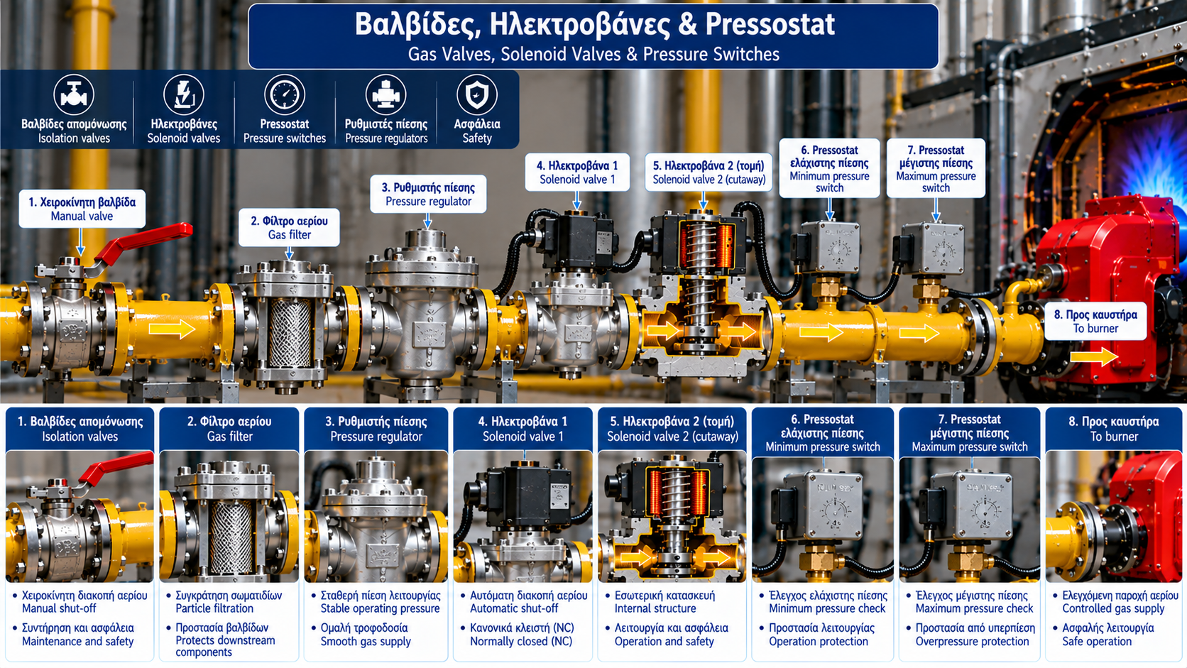
Natural Gas Solenoid Valves: Operation, Safety and Common Faults
Natural gas solenoid valves are essential components in combustion control and safety systems.
They provide electrically controlled gas isolation or flow to burners, boilers and industrial thermal equipment.
In combustion installations, safety shut-off valves operate alongside burner management systems, gas pressure switches and flame supervision equipment.
Reliable valve operation is critical because a valve that fails to open may prevent burner startup, while a valve that fails to close tightly can create a serious safety hazard.
1. What Is a Natural Gas Solenoid Valve?
A solenoid valve is an electrically actuated valve.
Normally closed (NC) designs are commonly used for gas safety shut-off applications.
Without the required electrical power, the valve remains in its closed position.
When the burner control system energizes the actuator, the valve opens under the conditions specified by its design.
Actual operation depends on whether the valve uses direct or indirect actuation.
2. Main Valve Components
A typical solenoid valve may include:
Valve body.
Electromagnetic coil.
Movable armature or plunger.
Return spring.
Sealing element.
Valve seat.
Electrical connector.
Optional position indication.
Materials must be compatible with the gas, operating temperature and pressure conditions.
3. Normally Closed Valve Operation
De-energized State
Without electrical power, the return mechanism holds the closing element against its seat.
Gas flow is interrupted.
Energized State
When the specified voltage is applied, the magnetic actuator operates and the valve opens, provided the required operating conditions are met.
Loss of Electrical Power
When power is removed, the valve should return to its specified safe position.
However, automatic closing does not guarantee tight shut-off if internal mechanical damage or seat deterioration is present.
4. The Role of Solenoid Valves in a Gas Train
A gas train contains the components required to regulate, control and safely deliver gas to a burner.
Depending on the application, it may include manual isolation valves, filters, pressure regulators, gas pressure switches, automatic safety shut-off valves and valve proving systems.
The number and arrangement of components depend on burner design and applicable safety requirements.
5. Why Are Two Safety Shut-Off Valves Used?
Many combustion installations use two automatic gas shut-off valves installed in series.
This arrangement provides additional isolation capability.
Some systems also incorporate valve proving equipment to detect unacceptable leakage.
The presence of two valves does not justify continued operation when one valve has failed.
6. Valve Stuck Closed
A valve that fails to open may prevent burner ignition.
Symptoms can include startup failure, insufficient downstream gas pressure and burner control alarms.
Possible causes include incorrect voltage, damaged coils, mechanical obstruction, contamination, unsuitable differential pressure and control system faults.
Troubleshooting should begin with alarm history and verification of the specified operating conditions.
7. Valve Stuck Open or Leaking
A valve that cannot close properly presents a serious safety concern.
Potential causes include mechanical sticking, foreign particles, damaged sealing elements and internal component failure.
Two conditions must be distinguished:
Mechanically stuck open: The closing element fails to return to its intended position.
Internal leakage: The valve closes mechanically but does not achieve the required tightness.
Both conditions require qualified technical investigation.
If the valve fails to provide the required safe shut-off performance, the installation must be taken out of service according to the prescribed procedures.
8. Solenoid Coil Failures
Coils can fail because of overheating, incorrect voltage, insulation deterioration or environmental damage.
Diagnostic checks may include supply voltage, electrical connections and specified electrical characteristics.
Replacement coils must be approved for the particular valve model and operating conditions.
Mechanical compatibility alone is not sufficient.
9. Valve Proving Systems
Valve proving systems are used to verify the required tightness of automatic gas shut-off valves.
Depending on system design, pressure changes in a defined section of the gas train are monitored.
The testing sequence depends on the valve arrangement, proving device and manufacturer instructions.
Valve proving systems must not be bypassed to permit burner startup.
10. Troubleshooting Procedures
Troubleshooting must be performed by appropriately qualified and authorized personnel.
A structured inspection may include:
Reviewing burner alarms.
Confirming gas pressure conditions.
Checking electrical supply.
Inspecting electrical connections.
Reviewing the operating sequence.
Performing approved tightness checks.
Recording findings and corrective actions.
Testing must not create uncontrolled gas releases.
Safety interlocks must not be bypassed for diagnostic convenience.
11. Preventive Maintenance
Preventive maintenance includes visual inspection, electrical connection checks and monitoring of operating behavior.
Tightness verification and safety shut-off testing must follow approved procedures.
Inspection intervals depend on manufacturer requirements, operating conditions and applicable regulations.
Unauthorized dismantling or the use of unapproved parts can compromise valve safety.
12. Applicable Technical Standards
Relevant standards include:
EN 161: Automatic shut-off valves for gas burners and gas appliances.
EN 676: Forced draught burners for gaseous fuels within the standard’s scope.
EN 1643: Valve proving systems for automatic shut-off valves used with gas burners and appliances.
Applicability depends on equipment design and the relevant regulatory framework.
Conclusion
Natural gas solenoid valves are critical components of burner safety systems.
Reliable operation requires proper selection, suitable electrical supply, compatibility with operating pressure and regular inspection.
Failure to open can interrupt operation, while failure to close tightly is a significant safety concern.
Correct troubleshooting, manufacturer-approved maintenance and protection against safety interlock bypassing are essential for safe gas installation operation.