
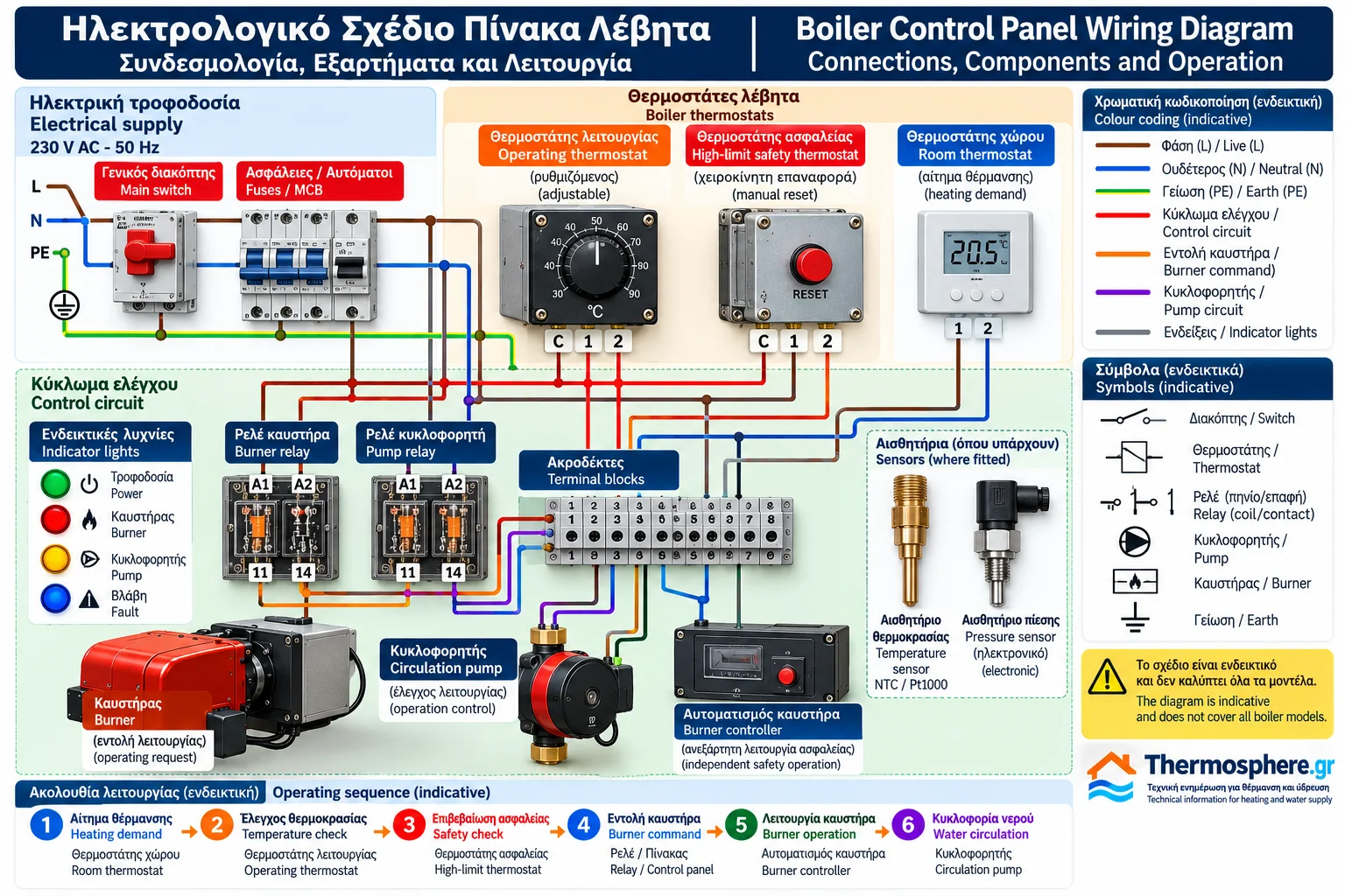
Boiler Control Panel Wiring Diagram: Components, Connections and Operation
The electrical control panel is a fundamental part of a conventional heating boiler. It provides the interface between the electrical supply, temperature controls, protective devices, burner controller and circulation pump.
Understanding the electrical diagram is essential for interpreting the boiler's operating sequence, identifying the purpose of each component and diagnosing electrical faults.
A wiring diagram represents the electrical connections of a particular system. A functional schematic, by contrast, primarily explains how the components interact. Neither necessarily shows their actual physical locations.
This guide explains the main electrical circuits, common symbols, control devices and operating principles of conventional boiler control panels.
The principles apply to many heating boilers equipped with separately mounted oil or gas burners. However, the actual arrangement depends on the appliance and burner manufacturer.
Important: There is no universal wiring diagram suitable for every boiler. Actual electrical connections must follow the approved manufacturer documentation.
1. What Is a Boiler Wiring Diagram?
A boiler wiring diagram is a technical representation of the electrical circuits associated with the boiler and its control equipment.
It may include:
Electrical power supply.
Operating switches.
Circuit protection devices.
Operating thermostat.
High-limit safety thermostat.
Room thermostat or external heating demand.
Relays and contactors.
Terminal blocks.
Burner control interface.
Circulation pump.
Indicator lights.
Sensors and electronic controllers.
The diagram helps technicians understand the operating logic and identify the relationship between electrical components.
It also supports maintenance documentation and systematic fault investigation.
2. Single-Line, Multi-Line and Functional Diagrams
Single-Line Diagram
A single-line diagram provides a simplified overview of the electrical distribution system.
A single line may represent a circuit containing several conductors.
This type of diagram is particularly useful for identifying supply arrangements and electrical protection.
Multi-Line Wiring Diagram
A multi-line diagram shows individual conductors and connections in greater detail.
It helps technicians understand the actual electrical relationships between terminals and components.
Functional Diagram
A functional diagram focuses on operating logic.
It shows how heating demand, temperature control, safety conditions and equipment commands interact.
A complete technical assessment may require more than one type of diagram.
3. Boiler Electrical Power Supply
Many conventional heating boilers use a single-phase 230 V AC, 50 Hz electrical supply.
Other supply configurations are possible, particularly in larger installations.
Common conductor designations include:
L: Line or live conductor.
N: Neutral conductor.
PE: Protective earth conductor.
The protective earth conductor performs a different function from the neutral conductor.
It must not be used as a normal operating current return path.
The correct supply voltage, frequency and connection requirements must be confirmed from the equipment nameplate and technical documentation.
4. Main Switch and Electrical Isolation
The main operating switch allows normal control panel operation to be enabled or disabled.
Depending on the design, it may be a single-pole or multipole switch.
However, the normal operating switch is not necessarily an approved electrical isolation device.
Electrical maintenance requires appropriate isolation, prevention of unintended re-energisation and verification that the relevant circuits are de-energised.
These procedures must be performed by competent personnel.
5. Fuses and Electrical Protection Devices
A boiler control panel may incorporate fuses or other overcurrent protection devices.
Protection requirements depend on:
Rated current.
Operating voltage.
Short-circuit breaking capacity.
Conductor size and installation conditions.
Electrical load characteristics.
Manufacturer requirements.
Electrical overcurrent protection is different from boiler overtemperature protection.
It also does not replace the safety functions of the burner controller.
Each protective device addresses a specific type of hazard.
6. Operating Thermostat in the Wiring Diagram
The operating thermostat monitors boiler water temperature and participates in normal heat production control.
In a functional diagram, it may be represented as a temperature-operated electrical contact.
When heating is required and water temperature is below the operating limit, the thermostat may permit a burner operating request.
When the selected limit is reached, the thermostat changes contact state.
The precise switching behaviour depends on the thermostat model and wiring arrangement.
Contact numbering and reference states must be verified using the manufacturer's documentation.
7. High-Limit Safety Thermostat
The high-limit safety thermostat provides protection against excessive boiler water temperature.
In conventional systems, it may form part of an approved protective interlock circuit that interrupts combustion.
Its protective function must be compatible with the boiler and burner safety architecture.
A high-limit safety thermostat must not be treated as an ordinary operating switch.
Depending on the device, activation may require manual reset after the cause of overheating has been identified and corrected.
8. Room Thermostat and Heating Demand
The room thermostat indicates whether the building requires heat.
Simple installations may use a switching contact.
More advanced installations may employ electronic controllers or digital communication.
Important: A boiler thermostat input is not necessarily designed for 230 V.
Many electronic boilers require a volt-free contact or a manufacturer-specified low-voltage interface.
Applying an external voltage to an incompatible input can damage the controller or create a hazardous condition.
The electrical interface must always be confirmed before any connection is made.
9. Relays and Contactors
Relays allow a control circuit to operate another electrical circuit.
A conventional electromechanical relay includes:
An operating coil.
Common contacts.
Normally open contacts.
Normally closed contacts.
In technical diagrams, relays may be designated K1, K2 or similar identifiers.
These designations are examples and are not universal.
A relay coil and its associated contacts may appear in different locations within the same schematic.
Matching component references allow the reader to identify which contacts belong to each relay.
Contactors are commonly used where electrical load requirements exceed the capabilities of smaller control relays.
10. Electrical Interface With the Burner
A boiler equipped with a separately mounted burner typically interfaces with a dedicated burner controller.
Depending on the equipment, the boiler panel may provide:
Electrical supply where specified.
An operating request.
A permissive signal.
Status monitoring.
Fault indication.
The burner controller is responsible for the combustion safety functions assigned to it.
These may include:
Managing the startup sequence.
Controlling ignition.
Supervising the flame.
Controlling fuel valves.
Performing safety shutdown.
Managing burner lockout conditions.
The boiler panel must not be confused with the dedicated burner safety controller.
Terminal assignments and safety sequences depend on the exact burner model.
11. Circulation Pump Control
The circulation pump moves heating water through the hydronic system.
It may be controlled by the boiler panel or by an independent heating controller.
Possible operating strategies include:
Running whenever heating is requested.
Starting after a minimum boiler temperature is reached.
Delayed activation or shutdown.
Pump overrun after combustion stops.
Operation based on heating zone demand.
Modern electronic pumps may also support speed-control signals or digital communication.
The electrical power supply and the control signal are separate functions and must not be confused.
12. Indicator Lights
Indicator lights provide information about the operating state of the boiler system.
Typical indications may include:
Electrical supply available.
Heating demand active.
Burner operating request.
Circulation pump operation.
Protective device activation.
General fault.
The meaning of an indicator depends on how it is connected.
For example, a light showing that the burner has received an operating request does not necessarily prove that a flame has been established.
Actual combustion status requires appropriate confirmation from the burner control system.
13. Terminal Blocks and Terminal Designations
Terminal blocks provide organised connection points between the control panel and external equipment.
A schematic may use references such as:
X1: Terminal block assembly.
X1:1: First terminal of the assembly.
X1:2: Second terminal of the assembly.
These are illustrative naming conventions.
They must not be interpreted as standard terminal numbers for all boilers.
The correct terminal assignments must be taken from the specific approved wiring diagram.
14. Power Circuits and Control Circuits
Boiler electrical systems often contain two broad categories of circuits.
Power Circuits
Power circuits supply electrical energy to loads such as motors, pumps and other equipment.
Control Circuits
Control circuits carry operating commands and signals between thermostats, relays, sensors and controllers.
Control circuits may operate at different voltages from the main power circuits.
It must not be assumed that every control circuit uses a low voltage.
Correct voltage identification is essential for electrical safety and equipment compatibility.
15. Illustrative Boiler Control Sequence
The following example explains the functional relationship between the main control components.
Step 1 — Heating Demand
A room thermostat or external controller requests heating.
Step 2 — Temperature Evaluation
The operating thermostat or electronic controller checks boiler water temperature.
Step 3 — Safety Conditions
The relevant protective devices must permit operation.
Step 4 — Burner Operating Request
The boiler control system sends an operating request to the burner controller.
Step 5 — Burner Safety Sequence
The burner controller performs its approved startup and combustion supervision sequence.
Step 6 — Heat Production
Combustion transfers thermal energy to the boiler water.
Step 7 — Water Circulation
The circulation pump operates according to the installed hydraulic and control strategy.
Step 8 — Temperature Regulation
The operating thermostat or electronic controller adjusts or interrupts heat production when the required conditions are reached.
This sequence is illustrative.
Certain boilers may require confirmed water flow, pump operation or other permissive conditions before combustion can begin.
It is not a wiring instruction or a universal operating sequence.
16. How to Read a Boiler Wiring Diagram
A systematic interpretation begins with identifying the exact equipment and document version.
A useful technical review follows these stages:
Identify the boiler manufacturer and model.
Confirm the wiring diagram revision.
Identify the electrical supply and voltage levels.
Locate the protective earth connections.
Identify switches and overcurrent protection devices.
Locate the normal temperature control circuit.
Identify protective interlocks and safety devices.
Match relay coils with their associated contacts.
Identify terminal blocks and external connections.
Locate the burner and circulation pump interfaces.
Compare the electrical diagram with the manufacturer's functional description.
This method supports fault analysis without relying on assumptions about unknown terminals.
17. Common Electrical Faults
The Control Panel Does Not Power On
Possible causes include a missing electrical supply, an activated protective device or an internal electrical fault.
Power Is Available but the Burner Does Not Start
There may be no heating demand, the boiler may already be at its temperature setpoint, or a protective device may be preventing operation.
A fault in the burner controller is another possibility.
A Relay Does Not Operate
Possible causes include a missing control command, a defective coil or a controller problem.
The Circulation Pump Does Not Run
The fault may involve the control output, electrical supply, pump itself or the operating conditions required for activation.
Intermittent Electrical Faults
Potential causes include loose terminals, damaged contacts, moisture or deteriorated wiring.
These symptoms are not sufficient to identify a defective component without further investigation.
18. Safe Electrical Inspection
Electrical inspection must be carried out by appropriately qualified personnel.
Essential precautions include:
Safe electrical isolation.
Prevention of unintended re-energisation.
Verification of the absence of voltage.
Use of suitable measuring instruments.
Reference to the approved wiring diagram.
Preservation of all protective devices.
Restoration of the equipment to its approved configuration.
Safety thermostats, flame supervision devices and other protective interlocks must not be bypassed to maintain boiler operation.
19. Conventional vs Electronic Boiler Control Panels
Conventional boiler panels commonly use mechanical thermostats, relays and electromechanical contacts.
Modern electronic panels use temperature sensors, microcontrollers, electronic outputs and programmed control logic.
Depending on the model, electronic controllers may provide:
Burner output modulation.
Weather-compensated temperature control.
Multiple heating circuit management.
Communication with external systems.
Fault history.
Advanced diagnostic functions.
Despite these differences, both types require suitable electrical protection and correctly designed safety functions.
20. Technical Documentation Required Before Maintenance
Before working on a boiler electrical system, the following information should be available:
Boiler installation and service manual.
Approved electrical wiring diagram.
Burner controller documentation.
Operating thermostat specifications.
Safety thermostat specifications.
Relay and protection device ratings.
Circulation pump technical data.
Electrical installation requirements.
Copying wiring arrangements from a different boiler model is not a reliable or safe practice.
Even visually similar panels may have different terminal assignments and control voltages.
Conclusion
The boiler control panel wiring diagram is an essential technical reference for understanding system operation and investigating electrical faults.
Correct interpretation requires a clear distinction between electrical supply, normal operating controls, protective devices and the independent burner safety controller.
The operating thermostat regulates heat production, the safety thermostat protects against excessive temperature, and the burner controller manages its assigned combustion safety functions.
A boiler wiring diagram is more than a collection of electrical connections. It documents the functional and protective architecture of the heating system.
This article is provided for technical information only. It is not a construction drawing or a set of wiring instructions. Electrical installation, testing and maintenance must be performed by qualified personnel according to applicable regulations and manufacturer documentation.
Thermosphere.gr — Technical information for heating and water supply.