
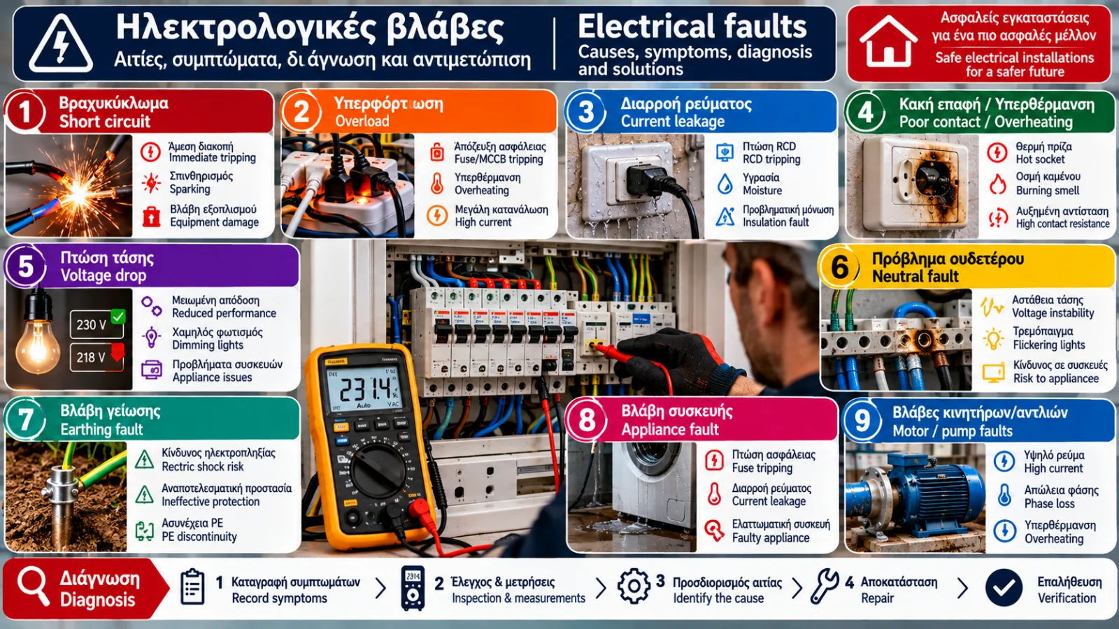
Electrical Faults: Complete Guide to Causes, Diagnosis and Solutions
Electrical faults are among the most important technical problems that can occur in a home or building.
A circuit breaker that repeatedly trips, a residual current device that disconnects the supply, an overheating socket or flickering lights may indicate different electrical problems.
Some faults simply interrupt the operation of an appliance. Others can create serious risks of electric shock, fire or damage to electrical equipment.
Correct fault management begins with recognizing the symptoms and continues with systematic technical diagnosis.
This guide examines the most common electrical faults, their possible causes, the methods professionals use to investigate them and the measures that can help prevent them.
1. What Is an Electrical Fault?
An electrical fault is an unwanted condition that affects the correct or safe operation of an electrical circuit, installation or appliance.
It may result from:
Damaged electrical conductors.
Insulation failure.
Loose electrical connections.
Excessive current consumption.
Defective electrical appliances.
Moisture.
Mechanical damage.
Improper installation.
Aging electrical equipment.
Electrical faults do not always produce the same symptoms.
Some cause an immediate interruption of the power supply, while others develop gradually without obvious warning signs.
2. Main Categories of Electrical Faults
Fault Category | Common Symptoms | Possible Causes |
|---|---|---|
Short circuit | Sudden circuit disconnection | Contact between conductors, insulation failure |
Overload | Protective device trips under load | Excessive combined electrical demand |
Current leakage | RCD trips | Moisture, insulation problems, faulty appliance |
Poor electrical contact | Heat, burning smell, intermittent operation | Loose or damaged connection |
Voltage drop | Reduced equipment performance | High load, excessive circuit impedance |
Neutral fault | Voltage instability, flickering lights | Loose or interrupted neutral connection |
Earthing fault | Increased electric shock risk | Protective conductor discontinuity, incorrect connection |
Protective device fault | Unwanted tripping or failure to operate | Defective or unsuitable protective device |
Symptoms alone do not establish the cause.
For example, a circuit breaker may trip because of an overload, a short circuit or another electrical problem.
3. Short Circuits: Causes and Symptoms
A short circuit occurs when an unintended low-impedance electrical connection develops between points at different electrical potentials.
In a single-phase circuit, for example, this may result from unintended contact between the live and neutral conductors.
Possible Causes
Damaged cable insulation.
Defective electrical components.
Incorrect wiring.
Water ingress.
Mechanical damage to conductors.
Electrical appliance failure.
Common Symptoms
A short circuit may cause:
Immediate circuit breaker operation.
Loss of power to a circuit.
Sparking.
Localized thermal stress.
Damage to electrical equipment.
How Is It Diagnosed?
An electrician evaluates the history of the incident, examines the relevant circuits and performs appropriate tests after safely isolating the installation.
Repeatedly resetting a protective device without investigating the cause is not an appropriate solution.
4. Electrical Circuit Overloads
An overload occurs when the current flowing through a circuit exceeds its permissible operating conditions.
An overload is not the same as a short circuit.
During an overload, current may increase because several electrical appliances operate simultaneously.
Calculation Example
Consider a hypothetical single-phase 230 V circuit supplying two purely resistive loads:
Electric heater: 2,000 W.
Second appliance: 1,800 W.
Total power:
P = 2,000 + 1,800
P = 3,800 W
Approximate current:
I = P / U
I = 3,800 / 230
I ≈ 16.5 A
If the circuit is designed for a lower permissible current, an overload may occur.
The actual response of the protective device depends on its characteristics and the circuit conditions.
How Are Overloads Addressed?
Corrective measures may include:
Evaluating connected loads.
Checking conductor cross-sections.
Verifying protective devices.
Redistributing electrical loads.
Installing additional circuits where necessary.
Replacing a circuit breaker with a higher-rated device without proper technical assessment can make an installation dangerous.
5. Why Does a Circuit Breaker Keep Tripping?
Repeated circuit breaker operation may indicate:
Overload.
Short circuit.
Defective electrical appliance.
Wiring problems.
Incorrect protective device selection.
A fault within the circuit breaker itself.
An Important Distinction
Immediate tripping may be associated with a high fault current.
Tripping after a period of operation may indicate thermal stress caused by an overload.
However, the tripping time alone does not prove the cause.
Professional investigation is necessary.
6. Current Leakage: Causes and Symptoms
Current leakage refers to electrical current flowing through paths other than the intended operating path.
Some electrical and electronic systems naturally produce small operating leakage currents.
A problem arises when leakage exceeds acceptable conditions or indicates a dangerous electrical fault.
Common Causes
Moisture inside electrical equipment.
Deteriorated insulation.
Defective heating elements.
Faulty appliances.
Incorrect electrical connections.
Wiring defects.
How Is Leakage Investigated?
An electrician may use:
Insulation resistance testing.
Residual current measurements.
Appliance testing.
Specialized circuit verification procedures.
The appropriate approach depends on the installation and the nature of the suspected fault.
7. Why Does an RCD Keep Tripping?
A residual current device (RCD) monitors the difference between the currents flowing through the live conductors of a protected circuit.
When its operating conditions are met, it disconnects the electrical supply.
Possible Causes of RCD Tripping
Appliance faults.
Moisture.
Insulation failure.
Accumulated operating leakage currents.
Incorrect neutral conductor connections.
Unsuitable RCD type.
A defective protective device.
Practical Example
An RCD protects several electrical circuits.
If multiple appliances produce small operating leakage currents, their combined residual current may contribute to unwanted tripping.
The solution is not to remove or bypass the RCD.
The installation requires appropriate testing and, where necessary, a review of its protective arrangement.
8. Poor Electrical Connections and Overheating
A loose, damaged or unsuitable electrical connection may have increased contact resistance.
When current flows through the connection, heat is generated.
For an ohmic resistance:
P = I² × R
Calculation Example
Suppose a defective connection has a resistance of 0.2 Ω and carries 10 A.
P = 10² × 0.2
P = 20 W
This power may be converted into heat within a very small area.
The example demonstrates why even relatively low contact resistance can produce significant localized heating.
Warning Signs
An unusually hot socket.
Discoloration.
Burning smell.
Intermittent operation.
Deformed plastic components.
Unusual sounds from an electrical connection.
These symptoms require prompt professional assessment.
9. Voltage Drop: Why Does Voltage Decrease?
Voltage drop occurs because conductors have electrical impedance and carry current.
Some voltage drop is normal in every real electrical circuit.
A problem may arise when it exceeds the applicable limits or affects equipment operation.
Possible Causes
Long cable runs.
Insufficient conductor cross-section.
High load current.
Poor electrical connections.
Supply voltage fluctuations.
Calculation Example
A single-phase circuit has a measured voltage of 230 V near the supply and 218 V at the load under specified operating conditions.
The difference is:
ΔU = 230 − 218
ΔU = 12 V
Percentage voltage drop:
ΔU% = (12 / 230) × 100
ΔU ≈ 5.2%
The result must be evaluated according to the reference points, measurement method and applicable requirements.
It does not independently prove the existence of a particular fault.
10. Why Do Lights Flicker?
Flickering lights can result from several different causes.
Possible Causes
Voltage fluctuations.
Unsuitable LED drivers.
Dimmer incompatibility.
Poor electrical connections.
Large varying electrical loads.
Defective light fittings.
Supply problems.
How Are the Symptoms Interpreted?
If only one light flickers, the investigation may focus on that fixture or its circuit.
If several lights flicker simultaneously, a wider section of the installation or the incoming supply may need to be examined.
Significant or sudden changes in brightness require particular attention.
11. Neutral Conductor Faults: A Particularly Dangerous Problem
The neutral conductor is a live conductor with a specific function in an electrical system.
A loose or interrupted neutral connection can cause serious problems.
Possible Symptoms
Unstable voltage.
Unexplained flickering.
Appliance malfunction.
Overheating connections.
Damage to electronic equipment.
Why Is This Dangerous in Three-Phase Installations?
In certain three-phase systems supplying unbalanced single-phase loads, an interrupted neutral can cause a significant shift in neutral-point potential.
This may result in dangerous overvoltages across some loads and undervoltages across others.
The exact behavior depends on the system configuration and operating conditions.
If a serious neutral fault is suspected, the affected installation should not remain in use until it has been assessed by a qualified professional.
12. Earthing and Protective Conductor Faults
The protective conductor (PE) and associated protective arrangements contribute to protection against electric shock.
Possible faults include:
Interrupted protective conductors.
Loose connections.
Inadequate equipotential bonding.
Problems with the earthing arrangement.
Incorrect electrical modifications.
Why Can These Faults Remain Hidden?
An electrical appliance may operate normally even when a serious protective conductor fault exists.
This is one reason electrical installations require professional testing.
A functioning socket does not prove that its protective earthing is effective.
13. Electrical Faults Caused by Moisture
Moisture can affect insulation, electrical connections and equipment operation.
Problems may develop in:
Bathrooms.
Kitchens.
Basements.
Storage rooms.
Outdoor sockets.
Junction boxes.
Pumps.
Outdoor lighting.
Possible Symptoms
RCD tripping.
Corrosion of metal components.
Intermittent operation.
Insulation failure.
Electrical component damage.
Electrical equipment affected by water must not be assumed safe simply because its exterior has dried.
14. Electrical Appliance Faults
Not every electrical fault originates in a building's fixed wiring.
An electrical appliance may cause:
Excessive current.
Leakage to earth.
Short circuits.
Overheating.
Unwanted protective device operation.
Common Examples
Electric water heaters.
Washing machines.
Dishwashers.
Electric ovens.
Pumps.
Electric heating appliances.
Professional diagnosis may involve examining both the appliance and its supply circuit.
15. Electric Motor and Pump Faults
Electric motors have operating characteristics that differ from those of simple resistive loads.
Possible problems include:
Overloading.
Supply faults.
Winding insulation failure.
Phase loss.
Inadequate protection.
Mechanical blockage.
Starting problems.
Practical Example
A pump may draw more current than expected because of increased mechanical resistance.
However, excessive current can also result from electrical defects or unsuitable supply conditions.
Diagnosis therefore requires evaluation of both electrical and mechanical characteristics.
16. Faults in Three-Phase Installations
Three-phase installations can experience problems that do not occur in the same way in single-phase circuits.
Common Problems
Phase loss.
Voltage imbalance.
Current imbalance.
Neutral conductor faults.
Uneven load distribution.
Three-phase motor problems.
Phase Loss
The loss of one phase can seriously affect three-phase motor operation.
Depending on operating conditions, it may cause:
Failure to start.
Reduced torque.
Increased current in the remaining phases.
Overheating.
Motors should be provided with protective arrangements appropriate to their application.
17. How Is Professional Electrical Fault Diagnosis Performed?
Electrical fault diagnosis should not rely on randomly replacing components.
A structured process is required.
Stage 1: Recording the Symptoms
The electrician gathers information about:
When the fault first occurred.
How frequently it appears.
Which appliances were operating.
Which protective devices operated.
Any recent installation changes.
Stage 2: Risk Assessment
The electrician determines whether there are indications of immediate danger.
Where necessary, the affected installation or circuit is safely isolated.
Stage 3: Visual Inspection
The inspection may include:
Distribution boards.
Electrical connections.
Wiring.
Protective devices.
Appliances.
Signs of overheating or moisture.
Stage 4: Targeted Measurements
Appropriate tests are selected according to the symptoms and installation characteristics.
Stage 5: Identifying the Cause
The findings are evaluated together to establish the most likely underlying cause.
Stage 6: Repair and Verification
After corrective work, the necessary tests are performed before the installation is safely returned to service.
18. Which Measurements Are Used for Fault Diagnosis?
Symptom | Possible Professional Tests |
|---|---|
Circuit breaker tripping | Load, insulation and protective device assessment |
RCD tripping | Insulation, residual current and RCD testing |
Flickering lights | Voltage measurements and connection assessment |
Overheating | Load, connection and thermal condition assessment |
Suspected neutral fault | Voltage and connection assessment by a qualified electrician |
Earthing problem | Continuity and protective measure verification |
Motor fault | Supply, current and insulation testing |
Excessive voltage drop | Measurements under load and circuit assessment |
Selecting and performing these tests requires professional competence.
Not every measurement method is suitable for every circuit or appliance.
19. Thermal Imaging for Electrical Fault Detection
Thermal imaging uses infrared radiation to visualize temperature distributions across surfaces.
It can help identify:
Overheating electrical connections.
Unusual temperature differences.
Overloaded components.
Potential problems in distribution boards.
Limitations
A thermal image does not independently establish the cause of a fault.
Interpretation is influenced by:
Electrical load.
Ambient temperature.
Material emissivity.
Reflections.
Operating conditions.
Thermal imaging complements electrical testing but does not replace the required verification procedures.
20. When Is an Electrical Fault an Emergency?
Certain symptoms require immediate attention.
Dangerous Warning Signs
Burning smells.
Smoke from a socket or distribution board.
Visible sparking.
Severe overheating.
Electric shocks from appliances.
Water entering electrical equipment.
Significant voltage fluctuations.
Signs of a serious neutral fault.
In these situations:
Do not touch suspicious electrical components.
Do not attempt repairs.
Stop using the affected equipment.
Isolate the electrical supply only if it is safe to do so.
Contact a qualified electrician.
If smoke or fire is present, move to safety and contact emergency services.
Do not use water on an electrical fire when equipment may still be energized.
21. How Can Electrical Faults Be Prevented?
Prevention depends on correct installation design, appropriate operation and required inspections.
Essential Preventive Measures
Arrange periodic professional electrical inspections.
Use suitable protective devices.
Ensure correct cable selection.
Avoid overloading sockets and extension leads.
Protect electrical equipment from moisture.
Replace damaged components promptly.
Obtain professional assessment before adding major electrical loads.
Investigate repeated protective device tripping.
Maintain the necessary electrical drawings and technical documentation.
Avoid improvised electrical modifications.
Preventive maintenance can reduce unplanned interruptions and improve electrical safety.
22. Frequently Asked Questions
Why Does a Circuit Breaker Trip When I Switch On an Appliance?
Possible causes include overload, short circuit, excessive starting current or an appliance fault. Professional investigation is required.
Why Does an RCD Trip for No Obvious Reason?
Possible causes include moisture, insulation deterioration, accumulated leakage currents or another electrical fault.
Is an Overheating Socket Dangerous?
Unusual overheating is a warning sign. Stop using the socket and have it inspected by an electrician.
Why Do Lights Dim When a Large Appliance Starts?
A temporary voltage drop may occur because of high starting current or other installation characteristics.
What Does It Mean When Lights Flicker Throughout the House?
The problem may involve the electrical supply, shared connections or another common part of the installation.
Can Damaged Wiring Cause a Fire?
Yes. Certain wiring faults can cause overheating or electrical arcing.
Why Does the RCD Trip When the Electric Water Heater Operates?
One possible cause is an insulation problem involving the heating element or another part of the circuit. Testing is required to establish the actual cause.
Is It Safe to Keep Resetting a Circuit Breaker?
Repeatedly resetting a protective device without identifying the cause is not a safe solution.
Can a Neutral Fault Damage Electrical Appliances?
Yes. Under certain conditions, neutral faults can cause dangerous voltage variations.
Can I Diagnose Electrical Faults Myself?
You can observe and describe symptoms, but electrical testing and repairs should be performed by appropriately qualified and authorized professionals.
Conclusion
Electrical faults can develop through different mechanisms and produce similar symptoms.
Short circuits, overloads, current leakage and poor electrical connections require different technical assessments.
Correct diagnosis relies on systematic symptom recording, visual inspection, appropriate electrical measurements and verification after corrective work.
Particular attention is required for neutral conductor faults, overheating connections, current leakage and repeated operation of protective devices.
Prevention, appropriate maintenance and timely professional intervention help reduce risks and maintain reliable electrical installation operation.
The correct way to address an electrical fault is not simply to eliminate the symptom temporarily, but to identify and correct its underlying cause.
Thermosphere.gr — Technical knowledge for safer and more efficient installations.
Disclaimer: This article is provided for educational and informational purposes. It is not a guide for performing electrical installation repairs. Electrical testing, modifications and repairs must be carried out by appropriately trained and authorized professionals.
Technical References
ELOT 60364 — Requirements for Electrical Installations in Greece.
IEC 60364-4-41 — Protection Against Electric Shock.
IEC 60364-4-43 — Protection Against Overcurrent.
IEC 60364-5-52 — Selection and Erection of Wiring Systems.
IEC 60364-6 — Verification.
IEC 61557 — Equipment for Testing, Measuring or Monitoring Protective Measures.
IEC 61010-1 — Safety Requirements for Electrical Measurement Equipment.
IEC 60050 — International Electrotechnical Vocabulary.
ELOT — Hellenic Organization for Standardization: https://www.elot.gr/
International Electrotechnical Commission: https://www.iec.ch/