
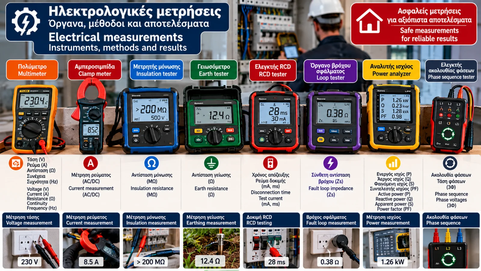
Electrical Measurements: Complete Guide to Instruments, Methods and Results
Electrical measurements are essential for understanding, diagnosing and evaluating the performance of electrical installations and equipment.
Using appropriate instruments, technicians can determine fundamental electrical quantities such as voltage, current, resistance, power and frequency.
More specialized applications involve insulation resistance measurements, earth resistance testing, fault loop impedance measurements and verification of protective devices.
However, accurate electrical measurement involves much more than reading a number on a display.
It requires selecting the correct instrument, understanding the measured quantity, applying a suitable method and interpreting the results correctly.
This guide presents the most important electrical measurement instruments, fundamental measurement principles, practical calculations and common mistakes.
1. What Electrical Quantities Can Be Measured?
The most common electrical quantities include:
Quantity | Symbol | Unit |
|---|---|---|
Voltage | U or V | Volt (V) |
Electric current | I | Ampere (A) |
Electrical resistance | R | Ohm (Ω) |
Active power | P | Watt (W) |
Electrical energy | E | Kilowatt-hour (kWh) |
Frequency | f | Hertz (Hz) |
Impedance | Z | Ohm (Ω) |
Insulation resistance | Riso | Megohm (MΩ) |
Power factor | PF | Dimensionless |
Each quantity describes a different characteristic of an electrical circuit.
Understanding these differences is essential for correctly interpreting measurement results.
2. Voltage Measurement
Electrical voltage represents the electric potential difference between two points.
It is measured in volts (V).
In typical residential electrical installations in Greece, the nominal supply voltage is 230 V between phase and neutral, and 400 V between phases in a three-phase system.
What Can Voltage Measurements Reveal?
Voltage measurements may help assess:
The presence of an electrical supply.
Voltage between specific conductors.
Voltage behavior under load.
Potential supply problems.
AC and DC Voltage
Alternating voltage (AC) periodically reverses polarity.
Direct voltage (DC) maintains a constant polarity under normal conditions.
Examples include:
Household electrical supply: AC.
Batteries: DC.
Many electronic circuits: DC.
The instrument and measurement function must be suitable for the type of voltage.
Safety note: Measuring voltage in energized installations involves electric shock hazards and requires appropriate professional training and protective measures.
3. Electric Current Measurement
Electric current represents the rate of electric charge flow.
It is measured in amperes (A).
Current depends on the applied voltage and the characteristics of the electrical load.
Calculation Example
Consider a purely resistive appliance rated at 2,000 W operating at 230 V.
The current is approximately:
I = P / U
I = 2,000 / 230
I ≈ 8.7 A
This simplified calculation assumes a power factor of 1.
For other types of loads, additional electrical characteristics must be considered.
4. Electrical Resistance Measurement
Electrical resistance describes how strongly a component opposes the flow of electric current.
It is measured in ohms (Ω).
For an ohmic component, Ohm's law states:
U = I × R
Therefore:
R = U / I
Calculation Example
If an ohmic component has a voltage of 12 V and a current of 2 A:
R = 12 / 2
R = 6 Ω
Where Is Resistance Measurement Used?
Testing resistive components.
Evaluating specific electrical parts.
Checking conductors.
Investigating faults in safely isolated circuits.
Resistance measurements using an ordinary multimeter must be performed only on appropriately isolated and safe circuits.
An ohmmeter function must never be applied to an energized circuit.
5. What Is a Digital Multimeter?
A digital multimeter is one of the most widely used electrical measuring instruments.
Depending on the model, it may measure:
AC voltage.
DC voltage.
Current.
Resistance.
Frequency.
Capacitance.
Circuit continuity.
Temperature.
What Does True RMS Mean?
For alternating electrical signals, the root mean square (RMS) value represents the equivalent heating effect of a signal in a resistive load.
A True RMS instrument can measure the RMS value of non-sinusoidal waveforms within the frequency, range and crest-factor limitations specified by its manufacturer.
This is particularly useful when measuring circuits containing electronic loads.
What Should You Consider When Choosing a Multimeter?
Measurement category.
Maximum rated voltage.
Accuracy.
Measurement range.
Resolution.
Suitable input fuses.
Compliance with relevant safety standards.
6. What Is a Clamp Meter?
A clamp meter measures electrical current using a sensor that surrounds a conductor.
In many applications, the conductor does not need to be disconnected to insert the instrument into the circuit.
Common Applications
Measuring motor current.
Checking electrical loads.
Evaluating appliance consumption.
Assessing current distribution.
Investigating electrical problems.
AC and AC/DC Clamp Meters
Not every clamp meter can measure direct current.
Some instruments use current transformers and are designed for AC measurements.
Others use Hall-effect sensors or alternative technologies to measure both AC and DC.
Why Does Conductor Selection Matter?
When measuring load current, the sensor must surround the appropriate conductor.
If conductors carrying opposing currents are enclosed together, their magnetic effects may cancel.
This explains why clamping around an entire multicore cable does not necessarily provide the load current.
7. Electrical Power Measurement
Electrical power describes the rate at which electrical energy is transferred or converted.
It is measured in watts (W).
Single-Phase AC Circuit
Active power is calculated as:
P = U × I × PF
Where:
P = Active power in watts.
U = RMS voltage.
I = RMS current.
PF = Power factor.
Calculation Example
Given:
U = 230 V
I = 5 A
PF = 0.8
Then:
P = 230 × 5 × 0.8
P = 920 W
Measuring voltage and current alone is not always sufficient to calculate active power accurately.
8. Active, Reactive and Apparent Power
In AC electrical systems, three important power quantities are distinguished.
Active Power (P)
Measured in watts (W).
It represents the rate at which electrical energy is converted into useful work, heat or other forms of energy.
Reactive Power (Q)
Measured in volt-amperes reactive (var).
It is associated with energy exchange between the source and components that store energy in electric or magnetic fields.
Apparent Power (S)
Measured in volt-amperes (VA).
For a single-phase circuit:
S = U × I
Power factor is defined as:
PF = P / S
For sinusoidal waveforms and linear loads:
PF = cosφ
For nonlinear loads, the overall power factor is also affected by waveform distortion.
9. Electrical Energy Measurement
The electrical energy consumed by an appliance depends on its power and operating time.
For constant power:
E = P × t
When power is expressed in kilowatts and time in hours, energy is expressed in kilowatt-hours.
Calculation Example
An appliance rated at 1.5 kW operates for four hours.
E = 1.5 × 4
E = 6 kWh
If the hypothetical electricity price is €0.20/kWh:
Energy cost = 6 × 0.20
Energy cost = €1.20
This calculation excludes other possible electricity bill charges.
For varying loads, consumption is determined by integrating power over time or using an appropriate energy meter.
10. Frequency Measurement
Frequency represents the number of cycles of a periodic signal per second.
It is measured in hertz (Hz).
The nominal electricity grid frequency in Greece is 50 Hz.
Frequency measurements may be used to assess:
Electrical power sources.
Generators.
Certain converters.
Control systems.
Measurement accuracy depends on the instrument and signal characteristics.
11. Insulation Resistance Measurement
Insulation resistance is an important quantity for evaluating the condition of electrical insulation.
It is measured using a specialized instrument known as an insulation resistance tester or megohmmeter.
What Does It Measure?
It evaluates resistance between selected conductive parts under a specified test voltage.
Which Units Are Used?
Common units include:
Kilohms (kΩ).
Megohms (MΩ).
Gigohms (GΩ).
Example
If an instrument displays 200 MΩ, the measured resistance is 200 million ohms.
However, this does not automatically mean that the circuit is safe.
Evaluation depends on:
Test voltage.
Circuit type.
Equipment condition.
Applicable requirements.
Insulation testing may involve voltages higher than the normal operating voltage of sensitive electronic components.
Appropriate isolation and equipment protection procedures are therefore essential.
12. Earth Resistance Measurement
Earth resistance measurement is used to evaluate the electrical connection between an earth electrode or electrode system and the surrounding ground.
It requires an appropriate earth resistance tester.
Which Methods Are Available?
Depending on the installation, methods may include:
Fall-of-potential testing.
Methods using auxiliary electrodes.
Selected clamp-based methods where the necessary conditions are satisfied.
Not every method is suitable for every earthing system.
Example
An earth resistance tester displays:
12 Ω
This value describes the measured resistance.
Whether it is acceptable cannot be determined without knowing the earthing system, protective devices and applicable requirements.
13. Continuity Measurement
Continuity measurement determines whether an electrical connection exists between two intended points.
In electrical installations, it is particularly important for protective conductors.
What Can Be Tested?
Protective conductors.
Equipotential bonding.
Connections between designated points.
Specific conductor paths.
A simple audible continuity indication from a multimeter does not necessarily replace the verification method required by the applicable electrical installation standard.
Professional testing requires suitable instruments and procedures.
14. Earth Fault Loop Impedance Measurement
Earth fault loop impedance is commonly represented by the symbol Zs.
It is an important parameter when evaluating automatic disconnection of supply in certain electrical protection systems.
What Does It Indicate?
The measurement provides information about the impedance of the fault-current return path.
Example
A tester displays:
Zs = 0.80 Ω
This value alone is insufficient to determine whether the result is acceptable.
The assessment must consider:
Earthing arrangement.
Voltage to earth.
Protective device characteristics.
Required disconnection times.
Measurement conditions.
Fault loop testing may involve applying a test current to an energized circuit and must be performed only by qualified professionals.
15. RCD Measurement and Testing
A residual current device (RCD) is used to provide protection under specified electrical fault conditions.
Professional testing may evaluate:
Rated residual operating current.
RCD type.
Disconnection time.
Response to specified test currents.
Compatibility with the installation.
Example
An RCD is marked:
IΔn = 30 mA
This represents its rated residual operating current.
An RCD tester may display disconnection time in milliseconds.
Whether the result is acceptable depends on the test performed, the device type and applicable limits.
There is no single universal acceptable disconnection time for every RCD and every test condition.
16. Measurements in Three-Phase Circuits
Three-phase electrical systems may require measurements of:
Phase-to-phase voltage.
Phase-to-neutral voltage.
Phase currents.
Neutral current.
Phase sequence.
Active power.
Power factor.
Load imbalance.
Three-Phase Power Calculation
For a balanced three-phase load:
P = √3 × ULL × IL × PF
Where:
ULL = Line-to-line voltage.
IL = Line current.
PF = Power factor.
Calculation Example
Given:
ULL = 400 V
IL = 10 A
PF = 0.9
P ≈ 1.732 × 400 × 10 × 0.9
P ≈ 6,235 W
P ≈ 6.24 kW
This formula applies to balanced conditions and should not be used indiscriminately for unbalanced loads.
17. Measurement Accuracy, Resolution and Uncertainty
Two instruments may display slightly different readings for the same electrical quantity.
This does not necessarily mean that one is defective.
Accuracy
Accuracy describes how close a measurement is to the true or reference value, within the instrument's specified characteristics.
Resolution
Resolution is the smallest displayed measurement increment.
For example, an instrument may display 230.1 V instead of 230 V.
However, additional displayed digits do not automatically indicate greater accuracy.
Measurement Uncertainty
Measurement uncertainty describes the dispersion of values that can reasonably be attributed to the measured quantity.
It may be influenced by:
Instrument characteristics.
Calibration.
Temperature.
Measurement method.
Installation conditions.
Human factors.
Correct technical evaluation requires more than reading the displayed number.
18. What Do CAT II, CAT III and CAT IV Mean?
Measurement categories relate to an instrument's ability to withstand transient overvoltages that may occur at different locations within an electrical installation.
CAT II
Associated with measurements at suitable points in circuits connected to electrical loads.
CAT III
Associated with measurements in parts of fixed electrical installations, including certain distribution circuits.
CAT IV
Associated with measurements at the origin of electrical installations and other locations requiring high resistance to transient overvoltages.
Instrument selection must not be based on the CAT designation alone.
Rated voltage, test leads, probes and overall equipment suitability must also be considered.
19. Instrument Calibration and Verification
Electrical measuring instruments must be maintained in suitable condition.
Calibration establishes the relationship between instrument indications and recognized reference values, allowing measurement deviations to be assessed.
Why Is Calibration Important?
An instrument may display readings without meeting the required measurement accuracy.
Measurement reliability depends on:
Instrument condition.
Correct operation.
Appropriate calibration.
Manufacturer instructions.
Measurement conditions.
The required calibration schedule depends on equipment use, quality requirements and applicable procedures.
20. Common Electrical Measurement Mistakes
Selecting the Wrong Instrument Function
Using an AC function for DC measurements or choosing an unsuitable range can produce incorrect results.
Using an Unsuitable Instrument
Equipment without the appropriate measurement category or voltage rating may be dangerous.
Measuring Resistance in an Energized Circuit
Using an ohmmeter function on a live circuit is dangerous and may damage the instrument.
Ignoring Power Factor
Applying P = U × I to every AC load can produce incorrect active power calculations.
Confusing Measurement Units
Ohms, kilohms and megohms represent significantly different resistance values.
Interpreting Results Without Technical Context
Measurements must be evaluated according to the installation, testing method and applicable requirements.
21. Comparison of Electrical Measuring Instruments
Instrument | Main Measurement | Typical Units |
|---|---|---|
Digital multimeter | Voltage, resistance and other quantities | V, Ω, A |
Clamp meter | Electric current | A |
Power meter | Active and other power quantities | W, VA, var |
Energy meter | Electrical energy | kWh |
Insulation tester | Insulation resistance | MΩ |
Earth resistance tester | Earth resistance | Ω |
Continuity tester | Resistance of protective connections | Ω |
Loop impedance tester | Fault loop impedance | Ω |
RCD tester | Disconnection time and operating characteristics | ms, mA |
Power quality analyzer | Voltage, current, harmonics and other parameters | V, A, %, Hz |
The actual capabilities of each instrument depend on its specific model.
22. Frequently Asked Questions
Which Instrument Is Used to Measure Voltage?
A suitable voltmeter or multimeter selected for the measurement conditions.
What Is the Difference Between a Multimeter and a Clamp Meter?
A multimeter generally uses test leads for most measurements, while a clamp meter can measure current using a sensor placed around a conductor.
Can a Multimeter Measure Earth Resistance?
An ordinary multimeter does not replace the appropriate instrument and professional method required for earth resistance testing.
What Does MΩ Mean?
One megohm equals 1,000,000 ohms.
What Does OL Mean on a Multimeter?
Depending on the instrument and selected function, it usually indicates an over-range condition or an open circuit.
Is True RMS Necessary?
It is particularly useful for accurately measuring non-sinusoidal signals within the instrument's specifications.
Can Power Be Calculated Using Only Voltage and Current?
Not always. In AC circuits, power factor must also be considered.
Is It Safe to Perform Measurements Inside an Electrical Distribution Board?
Measurements in energized distribution boards involve serious hazards and should only be performed by appropriately trained and authorized professionals.
When Does a Measuring Instrument Need Calibration?
Calibration intervals depend on manufacturer guidance, instrument use and application requirements.
Can One Measurement Prove That an Electrical Installation Is Safe?
No. Electrical safety is evaluated through a comprehensive process of inspection, testing and measurement.
Conclusion
Electrical measurements are fundamental tools for evaluating the operation and condition of electrical systems.
Multimeters, clamp meters, earth resistance testers, insulation testers and specialized installation testing instruments serve different purposes.
Correct instrument selection, understanding measurement units and recognizing the limitations of each method are essential for reliable results.
Measurement values must also be interpreted according to circuit characteristics, testing conditions and applicable technical requirements.
A reliable electrical measurement is not simply a number. It is a technical result obtained using an appropriate method and evaluated with the necessary knowledge.
Thermosphere.gr — Technical knowledge for safer and more efficient installations.
Disclaimer: This article is intended for educational and informational purposes. It is not a procedural guide for performing hazardous measurements on energized electrical installations. Professional electrical testing must be performed by appropriately trained and authorized personnel using suitable equipment and safety procedures.
Technical References
IEC 60364-6 — Low-Voltage Electrical Installations: Verification.
IEC 61557 — Electrical Safety in Low-Voltage Distribution Systems: Equipment for Testing, Measuring or Monitoring Protective Measures.
IEC 61010-1 — Safety Requirements for Electrical Equipment for Measurement, Control and Laboratory Use.
IEC 61010-2-030 — Particular Requirements for Equipment Having Testing or Measuring Circuits.
IEC 60529 — Degrees of Protection Provided by Enclosures.
ELOT 60364 — Requirements for Electrical Installations in Greece.
IEC 60050 — International Electrotechnical Vocabulary.
ELOT — Hellenic Organization for Standardization: https://www.elot.gr/
International Electrotechnical Commission — https://www.iec.ch/