
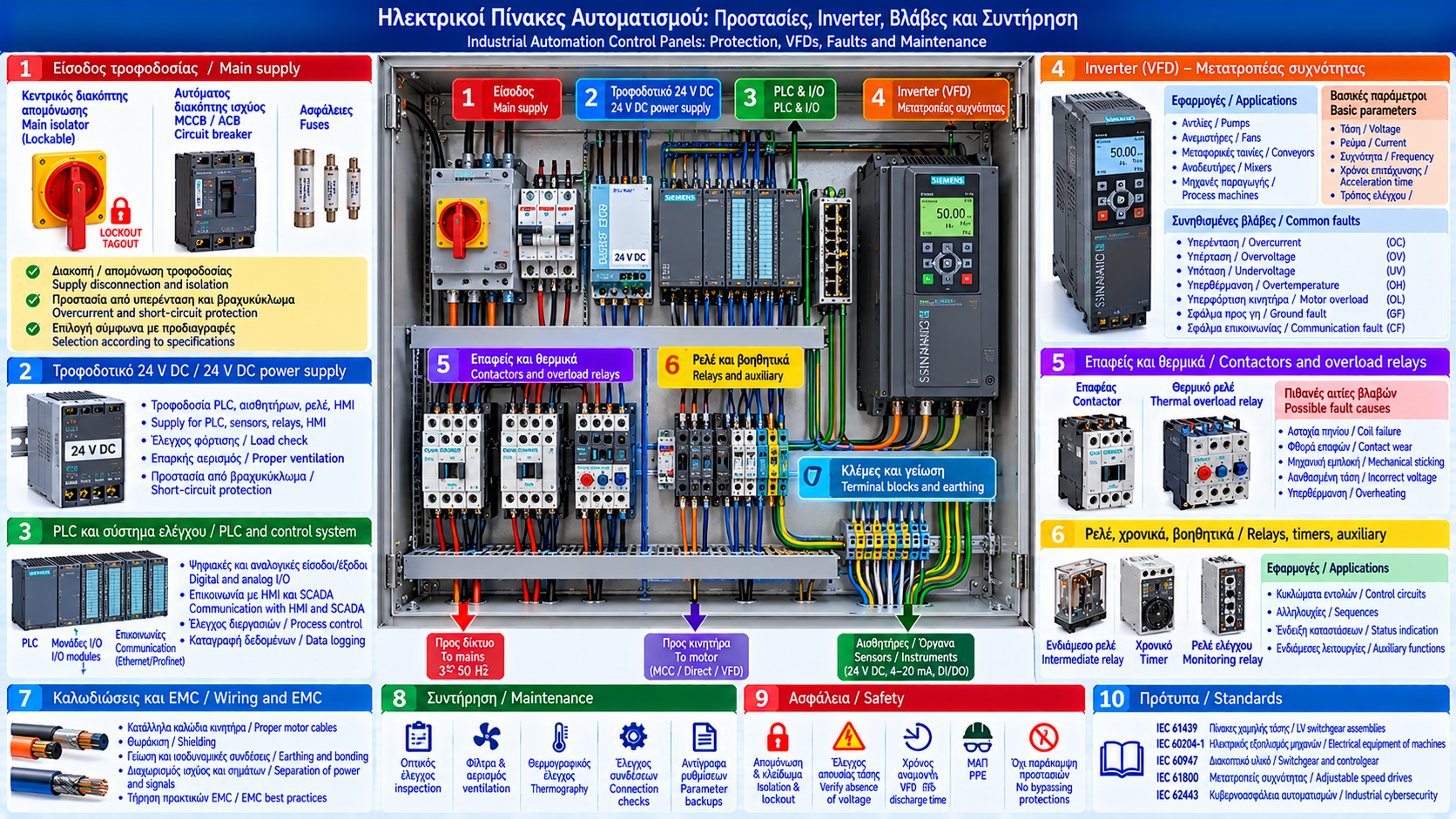
# Industrial Automation Control Panels: Protection, VFDs, Faults and Maintenance
## Introduction
Electrical control panels are essential components of industrial installations. They bring together power distribution, protection, control and communication equipment to coordinate machines and processes.
They are widely used in pumping stations, steam boiler plants, burner systems, water treatment facilities and manufacturing installations.
A control panel malfunction may cause production downtime, unwanted protective trips or loss of equipment control.
Understanding electrical components, variable-frequency drives and protective devices is essential for safe operation and effective maintenance.
## 1. What Is an Industrial Control Panel?
An industrial control panel is an assembly of electrical and electronic equipment used to control machinery or processes.
It may contain:
- Main disconnecting devices.
- Circuit breakers.
- Fuses.
- Contactors.
- Overload relays.
- Power supplies.
- PLCs and I/O modules.
- Variable-frequency drives.
- Control relays.
- Terminal blocks.
- Communication equipment.
The exact arrangement depends on the installation requirements.
## 2. Power Panels and Control Panels
Some facilities use separate panels for power distribution and automation.
Power panels may include:
- Supply breakers.
- Protective devices.
- Motor feeders.
- Power switching equipment.
Control panels may include:
- PLCs.
- 24 V DC power supplies.
- Input/output modules.
- Intermediate relays.
- Communication systems.
- Command circuits.
Smaller installations may combine these elements in one enclosure with appropriate segregation and design.
## 3. Motor Control Centers — MCC
A Motor Control Center is an assembly designed to supply and control electric motors.
It is commonly used when multiple motors must be managed from an organized electrical system.
An MCC may include:
- Motor feeders.
- Contactors.
- Circuit breakers.
- Electronic motor protection.
- Soft starters.
- VFDs.
- Measuring instruments.
- Communication systems.
Its design must consider electrical ratings, prospective short-circuit currents, environmental conditions and maintenance requirements.
## 4. Main Disconnecting Devices and Isolation
Main disconnecting devices are used to interrupt or isolate electrical supplies, depending on their type and certified capabilities.
Not all switches provide the same functions.
An isolating device must be suitable for its intended application and electrical conditions.
Switching a machine OFF from an HMI or issuing a PLC STOP command does not provide safe electrical isolation.
Before maintenance, appropriate hazardous energy isolation and verification procedures are required.
## 5. Circuit Breakers
Circuit breakers protect electrical circuits against specified overcurrent conditions.
Common categories include:
- MCB: Miniature Circuit Breaker.
- MCCB: Molded Case Circuit Breaker.
- ACB: Air Circuit Breaker.
Selection depends on:
- Rated current.
- Operating voltage.
- Breaking capacity.
- Load characteristics.
- Prospective short-circuit current.
- Protection coordination requirements.
A circuit breaker must not be selected solely from the motor rated current.
## 6. Fuses and Circuit Protection
Fuses protect electrical circuits according to their specific characteristics.
Applications may include:
- Control circuits.
- Power supplies.
- Power feeders.
- Semiconductor equipment when suitable fuse types are used.
Replacement requires verification of the correct type, voltage rating, current rating and operating characteristics.
Installing a higher-rated fuse without proper engineering assessment may defeat the intended protection.
## 7. Contactors
Contactors switch electrical loads, particularly motors.
Main components include:
- Coil.
- Main contacts.
- Auxiliary contacts.
- Operating mechanism.
Energizing the coil operates the contacts.
Common problems include:
- Coil failure.
- Contact wear.
- Mechanical sticking.
- Incorrect control voltage.
- Overheated connections.
Contactor selection must consider utilization category and load characteristics.
## 8. Thermal and Electronic Motor Overload Relays
Overload relays protect motors against specified overload conditions.
They may be:
- Thermal.
- Electronic.
Depending on the model, electronic relays may provide additional functions such as phase-loss, imbalance or thermal-state monitoring.
An overload relay does not automatically replace the required short-circuit protection.
Settings must reflect motor nameplate information, starting method and manufacturer guidance.
## 9. 24 V DC Power Supplies
24 V DC supplies commonly power:
- PLCs.
- Sensors.
- Relays.
- Operator interfaces.
- Communication modules.
- Control circuits.
Possible failure causes include:
- Overloading.
- High temperature.
- Inadequate ventilation.
- Input supply problems.
- Output short circuits.
- Component aging.
Sizing must consider total consumption and peak load requirements.
## 10. What Is a VFD?
A Variable Frequency Drive is an electronic converter that controls suitable electric motors by varying output frequency and voltage according to the selected control method.
Applications include:
- Pumps.
- Process fans.
- Conveyors.
- Mixers.
- Manufacturing machines.
In pumping systems, VFDs can adjust output to changing process demand.
Energy savings depend on the system curve, load characteristics and control strategy.
## 11. Basic VFD Operating Principle
A typical VFD includes:
1. Input rectifier.
2. DC intermediate circuit.
3. Output inverter stage.
4. Electronic control system.
The incoming electrical supply is converted to DC and then to a controlled alternating output.
Motor behavior depends on motor type, control method and drive parameters.
A VFD output should not be treated as an ordinary sinusoidal utility supply.
## 12. VFD Parameter Configuration
Important parameters may include:
- Motor rated voltage.
- Motor rated current.
- Rated frequency.
- Rated speed.
- Acceleration time.
- Deceleration time.
- Minimum and maximum frequency.
- Start command source.
- Speed reference source.
- Motor control method.
Values must reflect the motor nameplate, equipment specifications and application requirements.
Arbitrary parameter changes may cause malfunction or equipment stress.
## 13. Common VFD Faults
Typical fault categories include:
- Overcurrent.
- Overvoltage.
- Undervoltage.
- Overtemperature.
- Motor overload.
- Ground fault.
- Communication fault.
- External fault.
The exact meaning of a fault code depends on the manufacturer and model.
The same general description may represent different detection conditions.
## 14. Overcurrent Faults
An overcurrent indication may be associated with:
- Mechanical overload.
- Blocked machinery.
- Aggressive acceleration.
- Motor electrical problems.
- Cable faults.
- Incorrect parameters.
- Equipment failure.
Diagnosis should use the recorded fault code, operating data and manufacturer documentation.
Protection limits must not be increased arbitrarily to suppress the fault.
## 15. DC Bus Overvoltage and Undervoltage
The DC intermediate circuit is a key part of a VFD.
Faults may result from:
- Supply voltage fluctuations.
- Regenerative energy during deceleration.
- Power network problems.
- Incorrect settings.
- Component failures.
In some applications, rapid deceleration increases DC bus voltage.
Solutions depend on system design and may require suitable regenerative energy management.
## 16. Control Panel Overheating
High temperature reduces the reliability of electronic components.
Potential causes include:
- Blocked filters.
- Failed cooling fans.
- High ambient temperature.
- Insufficient cooling capacity.
- Excessive equipment density.
- Inadequate installation clearances.
Thermal management must follow manufacturer specifications and overall enclosure design.
## 17. Example: VFD-Controlled Pump Fails to Start
Consider a pump controlled by a VFD receiving a START command from a PLC but remaining stopped.
Troubleshooting checks:
1. Plant safety status.
2. VFD power supply.
3. Active fault codes.
4. Operating permissives.
5. Actual start command.
6. Speed reference source.
7. Motor condition.
8. Process requirements.
A zero speed reference or missing permissive may explain why the motor does not rotate despite a run command.
Checks must be performed by authorized personnel following manufacturer instructions.
## 18. Example: Contactor Operates but Motor Does Not Run
A contactor operating does not guarantee that the motor receives correct power.
Possible causes include:
- Missing power voltage.
- Main contact problems.
- Active protection.
- Broken conductor.
- Motor fault.
- Mechanical load problems.
Investigation requires electrical testing with suitable instruments and an approved safe-work procedure.
## 19. Electromagnetic Compatibility and VFDs
Variable-frequency drives generate rapid power switching.
Installation requires attention to:
- Suitable motor cables.
- Shielding.
- Grounding and bonding.
- Cable routing.
- Appropriate filters where required.
- Separation between power and signal circuits.
Poor installation may cause interference with sensors and communication systems.
EMC practices must follow manufacturer instructions and applicable standards.
## 20. Preventive Control Panel Maintenance
An organized maintenance program may include:
- Visual inspection.
- Filter and ventilation checks.
- Moisture and corrosion inspection.
- Power supply status checks.
- Fault history analysis.
- Cooling fan inspection.
- Cable inspection.
- Connection checks according to manufacturer guidance.
- Backup verification.
- Documentation updates.
Maintenance frequency depends on operating conditions, criticality and equipment specifications.
## 21. Thermographic Inspection
Thermography can help identify abnormal thermal behavior.
Potential findings include:
- Overheated connections.
- Unusual contact temperatures.
- Thermal stress in components.
- Temperature differences between comparable loads.
A thermal image alone does not establish the cause.
Interpretation requires knowledge of load, ambient conditions, emissivity and measurement limitations.
Inspection of energized panels requires an appropriate risk assessment and electrical safety precautions.
## 22. Standards and Technical Documentation
Depending on the installation, important references may include:
- IEC 61439: Low-voltage switchgear and controlgear assemblies.
- IEC 60204-1: Electrical equipment of machines.
- IEC 60947: Low-voltage switchgear and controlgear.
- IEC 61800: Adjustable speed electrical power drive systems.
- IEC 62443: Industrial automation and control system cybersecurity.
Applicability depends on equipment type, jurisdiction and regulatory requirements.
Technical documentation should include current drawings, equipment lists, settings and maintenance history.
## 23. Maintenance Safety
Electrical control panels may contain hazardous voltages and stored electrical energy.
Special care is required with VFD DC bus capacitors, which may remain charged after the input supply is disconnected.
Essential requirements include:
- Work by authorized and suitably trained personnel.
- Appropriate isolation and lockout procedures.
- Observing manufacturer-specified waiting periods.
- Verifying safe conditions and absence of hazardous voltage using approved procedures.
- Using suitable personal protective equipment.
- Avoiding unauthorized protection bypasses.
- Performing checks before returning equipment to service.
An OFF indication on a VFD display does not prove that its internal circuits are electrically safe.
## Conclusion
Industrial control panels combine protective devices, power circuits, PLCs, power supplies and variable-frequency drives to operate industrial equipment reliably.
Correct protection selection, suitable VFD configuration, thermal management and preventive maintenance reduce the likelihood of unplanned downtime.
Troubleshooting should rely on actual measurements, electrical drawings, fault history and manufacturer instructions.
Electrical safety must always take priority over restoration speed.
Thermosphere.gr – Technical Knowledge for Professionals.