
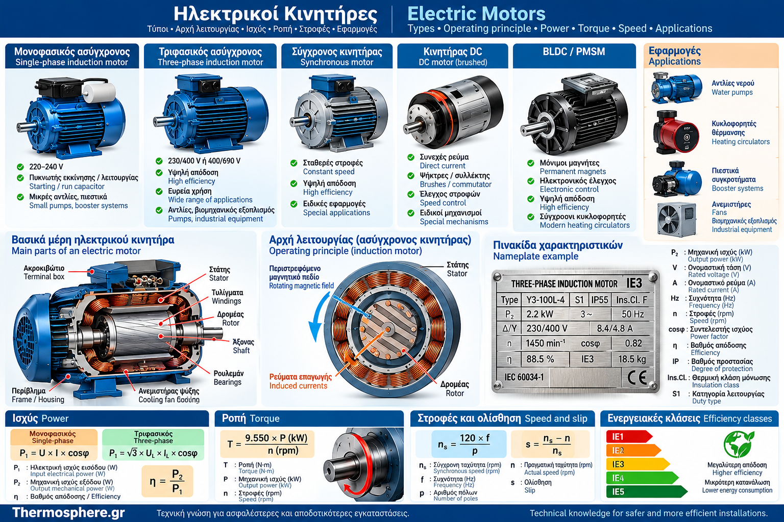
Electric Motors: Complete Guide to Types, Operating Principles, Power, Torque and Applications
Electric motors are fundamental components of modern electromechanical installations. They convert electrical energy into mechanical motion and are used in water pumps, heating circulators, pressure booster systems, industrial machinery and numerous other applications.
Although many motors have a similar external appearance, they can differ significantly in their operating principles, power supply requirements, starting methods, efficiency and speed-control capabilities.
Selecting the correct motor depends on more than its rated power. It requires an assessment of torque, rotational speed, load conditions, efficiency, electrical supply and installation environment.
This guide examines the main categories of electric motors, their technical characteristics, motor nameplate information and practical applications, with particular emphasis on water supply and heating installations.
1. What Is an Electric Motor?
An electric motor is an electromechanical machine that converts electrical energy into mechanical energy.
Mechanical energy is usually delivered as rotational motion through a shaft.
The shaft can drive:
Pump impellers.
Heating circulators.
Fans.
Compressors.
Conveyor belts.
Gearboxes.
Mechanical drive systems.
The energy conversion process is based on electromagnetic forces generated inside the machine.
Not all electrical energy is converted into useful mechanical power. Some energy is lost, mainly through heat generation and other electrical, magnetic and mechanical losses.
2. Main Components of an Electric Motor
Motor construction varies according to the technology, but many electric motors share several fundamental components.
Component | Function |
Stator | Stationary part involved in generating the magnetic field |
Rotor | Rotating part of the machine |
Shaft | Transfers mechanical motion |
Windings | Generate or interact with magnetic fields |
Magnetic core | Guides magnetic flux |
Bearings | Support rotation |
Housing | Provides mechanical protection |
Terminal box | Contains electrical connections, where applicable |
Cooling system | Removes part of the heat generated during operation |
Some motors also include permanent magnets, commutators, brushes, electronic converters or integrated sensors.
Stator and Rotor
The stator remains stationary while the rotor rotates.
Their electromagnetic interaction produces the torque required to drive the mechanical load.
3. How Does an Electric Motor Work?
The fundamental operating principle involves the interaction between electric current and magnetic fields.
When an appropriately designed electrical circuit generates a magnetic field, electromagnetic forces can develop and produce rotational motion.
In alternating-current motors, the magnetic field may vary or rotate.
In direct-current motors, the necessary electromagnetic interaction is achieved through different methods depending on the motor design.
Basic Operating Sequence
Electrical energy is supplied to the motor.
Magnetic fields are generated or activated.
Electromagnetic torque develops.
The rotor begins to rotate.
Mechanical power is transferred to the load.
The exact process differs between induction motors, synchronous motors and DC motors.
4. Main Types of Electric Motors
Electric motors can be classified according to their electrical supply and operating principles.
Motor Type | Main Characteristic | Typical Application |
Single-phase induction motor | Operates from a single-phase supply | Small water pumps |
Three-phase induction motor | Operates from a three-phase supply | Pumping stations |
Synchronous motor | Rotor rotates synchronously with the rotating magnetic field | Specialized industrial applications |
Brushed DC motor | Uses mechanical commutation | Mechanisms and specialized equipment |
BLDC motor | Uses electronic commutation | Modern circulators and drive systems |
PMSM | Permanent magnet synchronous motor | High-efficiency applications |
Stepper motor | Controlled movement in discrete steps | Automation systems |
The terms BLDC and PMSM often describe related permanent-magnet motor technologies. Their distinctions are mainly associated with motor design and electronic control methods.
5. Single-Phase Electric Motors
Single-phase motors are used in applications where a single-phase electrical supply is available.
Typical applications include:
Small water pumps.
Domestic pressure booster systems.
Small machinery.
Certain fans.
Auxiliary equipment.
Starting Characteristics
A typical single-phase induction motor does not develop sufficient starting torque when only its main winding is supplied from a single-phase source.
For this reason, suitable phase-shifting arrangements or other starting techniques are used.
Common Configurations
Capacitor-start motor.
Permanent-split-capacitor motor.
Capacitor-start, capacitor-run motor.
Split-phase motor with an auxiliary winding and starting switch.
The exact configuration depends on the motor design.
6. Three-Phase Electric Motors
Three-phase electric motors are widely used in installations with a three-phase power supply.
A three-phase supply can create a rotating magnetic field in the stator.
Advantages
Suitable for continuous operation in many applications.
Widely available.
Available across a broad power range.
Compatible with suitable variable-speed drives.
Well suited to many industrial applications.
Typical Applications
Water pumps.
Pressure booster systems.
Higher-power circulators.
Industrial machinery.
Water treatment installations.
The correct connection and starting method depend on the motor specifications and the characteristics of the electrical network.
7. Induction Motors
Induction motors are among the most widely used types of electric motors.
In a three-phase induction motor, the rotating magnetic field generated by the stator induces electric currents in the rotor.
The interaction between the magnetic fields produces torque.
Why Is It Called an Induction or Asynchronous Motor?
During normal motoring operation, the rotor rotates at a speed slightly lower than the synchronous speed of the rotating magnetic field.
This difference is necessary for currents to be induced in the rotor.
Main Advantages
Relatively simple construction.
High reliability.
Widespread use.
Broad availability of spare parts and technical support.
8. Squirrel-Cage Induction Motors
One of the most common induction motor designs is the squirrel-cage motor.
Its rotor contains conductive bars electrically connected by end rings.
Characteristics
No brushes are required to supply the rotor.
Robust construction.
Suitable for a wide range of applications.
Can be operated with a compatible inverter or variable frequency drive.
Applications
Squirrel-cage induction motors are used in pumps, compressors, machinery and numerous other electromechanical installations.
Robust construction does not eliminate the need for appropriate electrical protection or maintenance.
9. Synchronous Electric Motors
In synchronous motors, the rotor rotates in synchronism with the rotating magnetic field of the stator during steady synchronous operation.
Depending on the technology, the rotor may use:
Permanent magnets.
Electromagnetic excitation.
Specialized magnetic structures.
Where Are They Used?
High-efficiency applications.
Precision-control systems.
Modern pumping equipment.
Industrial installations.
Electronically controlled drive systems.
Many synchronous motors require suitable electronic control equipment for starting and speed regulation.
10. Direct-Current Motors (DC Motors)
DC motors operate from an appropriate direct-current power supply.
In a conventional brushed DC motor, current commutation is performed using brushes and a commutator.
Advantages
Speed-control capability.
Suitability for certain control applications.
Availability of different torque and speed characteristics.
Limitations
Brushed motors contain components subject to wear and may require maintenance.
Maintenance requirements depend on motor construction and operating conditions.
11. BLDC and Permanent Magnet Motors
Brushless DC motors use electronic commutation instead of the mechanical commutator found in conventional brushed DC motors.
Many related applications use a permanent-magnet rotor.
Main Characteristics
Electronic operation control.
Variable-speed capability.
No commutator brushes.
Potential for high energy efficiency.
Relationship to Modern Heating Circulators
Many modern heating circulators use permanent-magnet motors with electronic control.
The term ECM, meaning electronically commutated motor, is frequently used in the industry.
This technology allows circulator operation to be adapted to system requirements, depending on the motor design and available control functions.
12. Electric Motor Power
Power is one of the most important characteristics of an electric motor.
However, electrical input power must be distinguished from mechanical output power.
Electrical Input Power
This is the electrical power absorbed by the motor from its power supply.
Mechanical Output Power
This is the useful mechanical power delivered at the motor shaft.
For an electric motor:
η = P₂ / P₁
Where:
η = efficiency.
P₁ = active electrical input power.
P₂ = mechanical output power.
Calculation Example
Assume a motor has:
Electrical input power: 1,000 W.
Mechanical output power: 850 W.
Then:
η = 850 / 1,000 = 0.85
η = 85%
The difference represents the total energy conversion losses.
13. Calculating Electrical Power in Single-Phase and Three-Phase Motors
For a single-phase supply with sinusoidal voltage and current:
P₁ = U × I × cosφ
Where:
U = RMS voltage.
I = RMS current.
cosφ = power factor.
For a balanced three-phase system with sinusoidal quantities:
P₁ = √3 × Uₗ × Iₗ × cosφ
Where:
Uₗ = line-to-line voltage.
Iₗ = line current.
Three-Phase Motor Example
Assume:
Line-to-line voltage: 400 V.
Line current: 5 A.
Power factor: 0.82.
P₁ = √3 × 400 × 5 × 0.82
P₁ ≈ 2,841 W
This value represents the active electrical input power under the specified conditions.
It is not automatically equal to the mechanical output power at the shaft.
In systems with significant harmonic distortion, including certain electronically controlled drives, actual active power must be evaluated appropriately. The simplified expression using cosφ may not be sufficient.
14. Electric Motor Torque
Torque describes the rotational action produced by an electric motor.
It is measured in newton-metres (N·m).
Mechanical power is related to torque and angular velocity:
P = T × ω
Where:
P = mechanical power, in W.
T = torque, in N·m.
ω = angular velocity, in rad/s.
For rotational speed n expressed in revolutions per minute:
T = 9,550 × P / n
when P is expressed in kW.
Calculation Example
Assume a motor delivers:
Mechanical output power: 1.5 kW.
Rotational speed: 1,450 rpm.
Then:
T = 9,550 × 1.5 / 1,450
T ≈ 9.88 N·m
Why Is Torque Important?
A motor must develop sufficient torque to start and drive its connected load.
Rated power alone does not fully describe starting performance.
15. Motor Speed and Synchronous Speed
Rotational speed is usually expressed in revolutions per minute, or rpm.
In AC motors, the synchronous speed of the rotating magnetic field depends on the supply frequency and the number of poles.
nₛ = 120 × f / p
Where:
nₛ = synchronous speed, in rpm.
f = frequency, in Hz.
p = number of poles.
Example at 50 Hz
Number of Poles | Synchronous Speed |
2 | 3,000 rpm |
4 | 1,500 rpm |
6 | 1,000 rpm |
8 | 750 rpm |
The actual speed of an induction motor during normal motoring operation is generally slightly lower than these values.
16. What Is Induction Motor Slip?
Slip describes the relative difference between synchronous speed and the actual rotor speed.
s = (nₛ − n) / nₛ
Where:
s = slip.
nₛ = synchronous speed.
n = actual rotor speed.
Calculation Example
For a four-pole motor operating at 50 Hz:
nₛ = 1,500 rpm
If the actual rotor speed is 1,450 rpm:
s = (1,500 − 1,450) / 1,500
s = 0.0333
Slip ≈ 3.33%
Slip varies with load and motor characteristics.
Slip is not, by itself, an indication of a fault.
17. Motor Efficiency and IE Efficiency Classes
Energy efficiency affects the operating cost of an electric motor.
Motor efficiency classes are defined through applicable technical standards.
Common Efficiency Classes
IE1.
IE2.
IE3.
IE4.
IE5, for technologies and applications covered by the relevant specifications.
These classifications do not mean that every electric motor is automatically subject to the same efficiency classification system.
Applicability depends on motor type, rated power and the scope of the relevant standard.
Energy Consumption Example
Consider two motors delivering the same mechanical output power:
P₂ = 2.2 kW
Motor A
Efficiency: η = 85%
P₁ = 2.2 / 0.85 ≈ 2.588 kW
Motor B
Efficiency: η = 92%
P₁ = 2.2 / 0.92 ≈ 2.391 kW
Difference:
ΔP ≈ 0.197 kW
For 3,000 operating hours per year, assuming the same constant mechanical output:
ΔE = 0.197 × 3,000
Energy savings ≈ 591 kWh/year
This is an illustrative calculation.
Actual savings depend on the operating load profile and real motor efficiencies.
18. Understanding an Electric Motor Nameplate
A motor nameplate provides essential information for correct selection, electrical connection and protection.
Common Nameplate Information
Marking | Meaning |
P₂ / kW | Rated mechanical output power |
V | Rated voltage |
A | Rated current |
Hz | Frequency |
rpm / min⁻¹ | Rated rotational speed |
cosφ | Power factor |
η / IE | Efficiency or efficiency class |
Δ / Y | Permitted winding connections, where applicable |
IP | Enclosure protection rating |
Insulation class | Thermal classification of the insulation system |
Duty / S1, etc. | Duty type |
Important Note
Nameplate ratings apply under the conditions specified by the manufacturer.
The correct winding connection must never be assumed solely from the appearance or arrangement of the terminals.
19. Operating Conditions, Cooling and Protection Ratings
Motor performance and service life are significantly affected by the installation environment.
Ambient Temperature
High ambient temperatures may reduce the available thermal margin of a motor.
Cooling Methods
Cooling may be achieved through:
Natural air circulation.
An integrated cooling fan.
An external cooling system.
Liquid circulation in specialized applications.
IP Protection Rating
The IP rating describes the enclosure’s protection against the ingress of solid objects and water.
It does not independently establish suitability for corrosion, chemical exposure or high-temperature environments.
Duty Type
An electric motor may be designed for continuous, intermittent or other operating duties.
Selection must account for the actual operating cycle.
20. Electric Motors in Water Pumps and Heating Circulators
Pumps are among the most important applications of electric motors within the technical scope of Thermosphere.gr.
Water Pumps
The motor rotates the impeller or another pumping mechanism.
The mechanical power required depends on the hydraulic operating conditions.
For a pump:
Pₕ = ρ × g × Q × H
Where:
Pₕ = hydraulic power, in W.
ρ = fluid density, in kg/m³.
g = gravitational acceleration, in m/s².
Q = flow rate, in m³/s.
H = pump head, in m.
Calculation Example
For water with:
ρ ≈ 1,000 kg/m³.
g ≈ 9.81 m/s².
Q = 0.002 m³/s.
H = 20 m.
Pₕ = 1,000 × 9.81 × 0.002 × 20
Pₕ ≈ 392 W
This represents hydraulic power.
The mechanical shaft power required is higher because of pump losses.
Electrical input power is additionally affected by motor efficiency and the efficiency of any electronic converter.
Heating Circulators
Modern heating circulators may incorporate electronic speed control and adapt their operation to the requirements of the hydraulic system.
Typical control strategies include:
Constant differential pressure.
Proportional differential pressure.
Constant speed.
Automatic adaptation, where supported.
Correct selection depends on the required flow rate and head of the hydraulic network.
21. How to Select the Right Electric Motor
Motor selection should be based on more than rated power.
Main Selection Criteria
Required mechanical output power.
Required torque.
Rated rotational speed.
Load starting characteristics.
Available electrical supply.
Required control method.
Environmental conditions.
Operating duty.
Energy efficiency requirements.
Protection requirements.
Maintenance and technical support availability.
Compatibility with the driven equipment.
Example of Incorrect Motor Selection
A motor may have sufficient rated power but inadequate starting torque for a particular load.
Similarly, a motor with the correct power rating may be unsuitable for the installation environment or intended operating duty.
Correct selection requires a combined assessment of all relevant characteristics.
22. Frequently Asked Questions About Electric Motors
1. What Is the Difference Between a Single-Phase and a Three-Phase Motor?
The main difference is the electrical supply and the method used to create the magnetic field.
Motor construction and starting methods may also differ.
2. What Is an Asynchronous Motor?
An asynchronous motor is one in which rotor speed differs from the synchronous speed of the rotating magnetic field.
3. What Is Motor Slip?
Slip is the relative difference between the synchronous speed and actual rotor speed of an induction motor.
4. What Does the kW Rating on a Motor Nameplate Mean?
For conventional industrial motors, it generally indicates rated mechanical output power under the conditions specified by the manufacturer.
5. Why Does a Motor Consume More Electrical Power Than the Mechanical Power It Delivers?
Because electrical, magnetic and mechanical losses occur during energy conversion.
6. What Is Electric Motor Torque?
Torque is the physical quantity that describes the rotational action produced by the motor.
7. Can the Speed of a Three-Phase Motor Be Changed?
Yes. In suitable applications, variable frequency drives, also known as inverters or VFDs, can be used.
8. What Is a BLDC Motor?
A BLDC motor uses electronic commutation instead of mechanical commutator brushes.
9. Why Do Modern Heating Circulators Often Consume Less Energy?
Many use efficient motors and electronic controls that adjust operation to the actual requirements of the heating system.
10. Is Rated Power Enough to Select an Electric Motor?
No. Torque, rotational speed, starting characteristics, electrical supply, efficiency and operating conditions must also be considered.
Conclusion
Electric motors are essential components of water supply systems, heating installations and electromechanical equipment.
Single-phase and three-phase induction motors are widely used, while modern permanent-magnet technologies and electronically controlled drives provide significant opportunities for improved control and energy efficiency.
Understanding an electric motor requires distinguishing electrical input power from mechanical output power, as well as evaluating torque, speed, slip and efficiency.
The motor nameplate is a fundamental source of technical information, but selection must also account for the actual mechanical load and operating conditions.
The right electric motor is not simply the one with enough kilowatts. It is the motor capable of starting, driving and controlling the intended load safely, reliably and efficiently.
Thermosphere.gr — Technical knowledge for safer and more efficient installations.
Important Safety Notice
This article is intended for educational and informational purposes.
Electrical connections, motor interventions, testing and maintenance must be carried out by appropriately trained and licensed professionals.
Before any work begins, suitable safe-isolation procedures must be implemented. Hazards associated with moving parts, hot surfaces and stored energy must also be considered.
Technical References and Standards
IEC 60034-1 — Rotating Electrical Machines: Rating and Performance.
IEC 60034-2-1 — Standard Methods for Determining Losses and Efficiency from Tests.
IEC 60034-5 — Degrees of Protection Provided by the Integral Design of Rotating Electrical Machines.
IEC 60034-6 — Methods of Cooling.
IEC 60034-7 — Classification of Types of Construction, Mounting Arrangements and Terminal Box Position.
IEC 60034-12 — Starting Performance of Single-Speed Three-Phase Cage Induction Motors.
IEC 60034-30-1 — Efficiency Classes of Line-Operated AC Motors.
IEC 60034-30-2 — Efficiency Classes of Variable Speed AC Motors.
IEC 60034-14 — Mechanical Vibration of Certain Machines.
IEC 61800 Series — Adjustable Speed Electrical Power Drive Systems.
IEC 60364 — Low-Voltage Electrical Installations.
Commission Regulation (EU) 2019/1781 — Ecodesign Requirements for Electric Motors and Variable Speed Drives, as amended and applicable.
International Electrotechnical Commission (IEC): https://www.iec.ch/
Hellenic Organization for Standardization (ELOT): https://www.elot.gr/
Note: The applicability of technical standards and energy-efficiency requirements depends on motor type, rated power, application scope, current editions and relevant exemptions.