
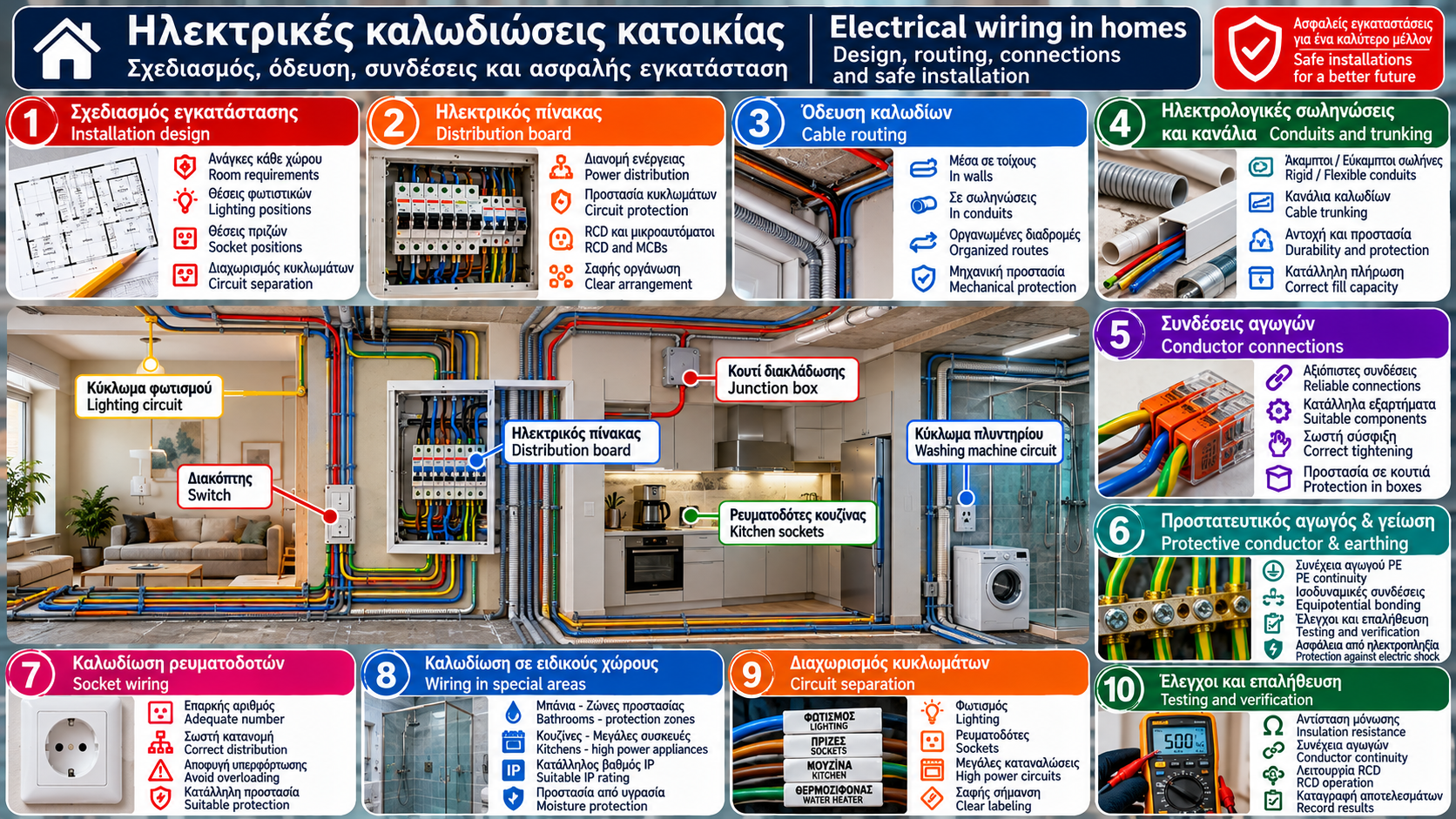
Electrical Wiring in Homes: Complete Guide to Design, Cable Routing, Connections and Safe Installation
Electrical wiring forms the fundamental infrastructure of every modern home. It carries electrical energy from the distribution board to lighting circuits, socket outlets, electrical appliances and permanently installed equipment.
A properly designed wiring installation must ensure not only the reliable operation of electrical appliances but also protection against electric shock, overheating, short circuits and fire.
The quality of an electrical installation does not depend exclusively on the cable used. Cable routing, conduit selection, electrical connections, circuit separation, protection against external influences and final verification are equally important.
This guide examines the essential principles of residential electrical wiring design and installation, focusing on technical accuracy and electrical safety requirements.
1. What Is Residential Electrical Wiring?
Residential electrical wiring consists of the conductors, cables, conduits, cable routes, connections and accessories that enable electrical energy to be distributed throughout a building.
It includes:
Supply circuits from the electrical distribution board.
Lighting circuits.
Socket-outlet circuits.
Circuits supplying high-power electrical loads.
Wiring for electrical appliances.
Protective conductors.
Junction and connection boxes.
Mechanical cable protection systems.
Wiring is part of a larger electrical installation and must be designed as an integrated system.
2. Main Components of an Electrical Wiring Installation
A typical installation includes different components, each performing a specific function.
Component | Main Function |
Electrical distribution board | Power distribution and circuit protection |
Electrical conductors | Carrying electrical current |
Cables | Assemblies of insulated conductors |
Electrical conduits | Protection and organized cable routing |
Junction boxes | Housing suitable electrical connections |
Device boxes | Installing switches and socket outlets |
Socket outlets | Connection points for portable appliances |
Switches | Control of electrical loads |
Protective conductors | Contributing to protection against electric shock |
The selection of each component depends on operating conditions and installation requirements.
3. Planning the Wiring Before Installation
Proper planning must take place before any installation work begins.
The following should be determined:
The electrical requirements of each room.
Lighting fixture locations.
Switch positions.
Socket-outlet positions.
Permanently installed electrical appliances.
Circuit routes.
Protection requirements.
Future expansion needs.
Why Is Planning Important?
Inadequate planning can result in:
Excessive use of power strips.
Unnecessarily long cable routes.
Difficult maintenance.
Poor load distribution.
Increased costs for future modifications.
Reduced functionality.
A properly prepared design enables organized installation and simplifies future inspections.
4. Separation of Electrical Circuits
It is not appropriate for every electrical load in a home to be supplied by a single common circuit.
The installation should be divided into suitable circuits according to their purpose, load and protection requirements.
Common Circuit Groups
Lighting.
General-purpose socket outlets.
Kitchen circuits.
Electric oven.
Electric water heater.
Washing machine.
Heat pump.
Water pumps.
Other permanently installed electromechanical equipment.
Circuit separation improves load management and can limit the extent of an interruption.
Example
If a fault develops in one socket-outlet circuit, suitable circuit separation may allow other independent circuits to continue operating.
The exact circuit arrangement must be determined by the electrical design rather than by applying the same number of circuits to every home.
5. Routing Electrical Cables Inside Walls
Cable routing refers to the path followed by conductors and cables from the distribution board to the points where electrical energy is used.
In concealed installations, cables are installed within suitable building structures and wiring systems.
Basic Principles
Routes should be planned systematically.
Unnecessary changes in direction should be avoided.
Suitable mechanical protection must be provided.
Structural elements must be considered.
Access for inspection must be provided where required.
Applicable separation requirements from other services must be respected.
Why Are Predictable Routes Preferred?
Clearly defined and documented cable routes reduce the risk of accidental cable damage during future drilling or the installation of furniture and equipment.
Routing must follow the applicable technical requirements and the project design.
6. Concealed and Surface-Mounted Wiring
There are two main installation approaches.
Concealed Wiring
Wiring is incorporated into suitable structures within walls, floors or other building elements.
Advantages:
Limited visual impact.
Protection against certain mechanical influences.
Clean architectural appearance.
Limitations:
Greater difficulty when making modifications.
Requires accurate planning during construction.
Repairs may involve work on building structures.
Surface-Mounted Wiring
Cables are routed through suitable surface-mounted trunking, conduits or other supporting systems.
Advantages:
Easier access.
Simpler extensions.
Reduced need for structural modifications.
Limitations:
Visible installation components.
Requires careful mechanical protection.
Requires appropriate fixing and support.
The most suitable approach depends on the building and its intended use.
7. Electrical Conduits and Cable Trunking
Conduits and cable trunking are used to organize and protect electrical wiring.
Main Categories
Rigid electrical conduits.
Flexible conduits.
Corrugated conduits.
Metallic conduit systems.
Plastic cable trunking.
Specialized systems for particular environmental conditions.
Selection Criteria
The selection process must consider:
Mechanical strength.
Temperature.
Moisture.
Resistance to external influences.
Compatibility with the wiring system.
Fire safety requirements.
Safe installation and maintenance access.
Using a conduit does not automatically mean that the wiring system is suitable for every application.
8. Conduit Fill and Cable Installation Capacity
A conduit should not be filled arbitrarily with as many conductors as can physically fit inside it.
Its dimensions must account for:
Number of conductors.
Their external dimensions.
Route length and configuration.
Bends.
Installation conditions.
Heat dissipation.
Manufacturers’ instructions.
Why Does This Matter?
Excessive conductor concentration can make installation and replacement difficult.
In addition, grouping several circuits together can affect thermal performance and current-carrying capacity.
Checking the available physical space alone is therefore insufficient.
9. Junction Boxes and Electrical Connections
Junction boxes are used to provide protected accommodation for electrical connections.
They must be selected according to:
Number of connections.
Required internal space.
Installation method.
Environmental conditions.
Required degree of protection.
Basic Principles
Electrical connections must:
Use suitable, appropriately certified components.
Provide adequate electrical and mechanical integrity.
Be protected from tensile stress.
Be protected against moisture and mechanical damage.
Remain accessible where required.
Improvised joints and the use of insulating tape as the sole means of making an electrical connection are not acceptable technical practices.
10. Connecting Electrical Conductors
Connection quality directly affects the safety and reliability of an electrical installation.
A poor connection can create increased electrical resistance.
The heat generated can be described by:
P = I² × R
Where:
P = power converted into heat, in watts (W).
I = electrical current, in amperes (A).
R = electrical resistance, in ohms (Ω).
Calculation Example
Suppose a defective electrical contact has a resistance of 0.1 Ω and carries a current of 12 A.
P = 12² × 0.1
P = 14.4 W
This heat may be generated within a very small area.
Technical Requirements
Connections must be compatible with:
Conductor material.
Conductor cross-sectional area.
Conductor construction.
Operating current.
Manufacturer instructions.
Correct tightening and the use of suitable terminals or connectors are essential.
11. Electrical Conductor Colour Identification
Conductor colour identification helps distinguish conductor functions and reduces the likelihood of wiring errors.
Modern AC installations commonly use the following identification colours:
Conductor | Common Identification |
Phase L1 | Brown |
Phase L2 | Black |
Phase L3 | Grey |
Neutral N | Blue |
Protective conductor PE | Green/yellow |
The exact application depends on the relevant standards and installation type.
Important: In older or modified installations, conductor colours cannot be treated as reliable proof of conductor function.
Identification must be verified using appropriate professional procedures.
12. Lighting Circuit Wiring
Lighting circuits supply luminaires and their associated control systems.
They may include:
Single-pole switches.
Two-way switching arrangements.
Control from multiple locations.
Dimmers.
Occupancy sensors.
Smart lighting controllers.
What Must Be Considered?
Suitable circuit arrangements.
Compatibility between switches and loads.
Conductor protection.
Correct protective conductor connections where required.
Access to maintenance points.
Modern LED Lighting
LED systems may have specific operating characteristics, including inrush currents and dimmer compatibility requirements.
The design must account for the actual characteristics of the equipment.
13. Socket-Outlet Wiring
Socket outlets provide connection points for portable and movable electrical appliances.
Their distribution should reflect how each room will be used.
Main Design Considerations
Adequate number of outlets.
Suitable locations.
Avoiding concentration of high electrical loads.
Required protection against electric shock.
Appropriate equipment selection.
Protection against external influences.
Why Should Power Strips Not Replace Proper Planning?
Permanent reliance on multiple extension leads can increase mechanical stress on electrical connections and may lead to overloading.
Socket outlets should be planned around the actual needs of the space.
14. Dedicated Circuits for High-Power Electrical Loads
Certain appliances require special consideration because of their electrical power or operating characteristics.
Examples include:
Electric ovens.
Electric water heaters.
Heat pumps.
Electric heating elements.
Water pumps.
Other high-power equipment.
What Must Be Evaluated?
For each appliance, the following should be assessed:
Rated power.
Operating current.
Starting current, where applicable.
Required protective measures.
Circuit route.
Manufacturer instructions.
Environmental conditions.
The need for a dedicated circuit must be determined by the technical requirements and installation design.
15. Protective Conductors and Equipotential Bonding
The protective conductor (PE) is an important component of measures intended to protect against electric shock.
It contributes to providing the intended fault-current path and supporting the effective operation of appropriate protective devices.
Basic Principles
Protective conductor continuity must be maintained.
Connections must be reliable.
The protective conductor must not be used as a normal operating current conductor.
Its cross-sectional area must comply with applicable requirements.
Equipotential bonding must be designed appropriately.
The presence of a green/yellow conductor does not, by itself, prove that the protective measures are effective.
Appropriate verification is required.
16. Separation of Power Wiring and Extra-Low-Voltage Systems
Modern homes often contain several different wiring networks.
Examples include:
230/400 V electrical power circuits.
Data networks.
Telecommunications wiring.
Video intercom systems.
Automation systems.
Sensor wiring.
Separating these systems is important for:
Electrical safety.
Reducing electromagnetic interference.
Maintenance.
Circuit identification.
Can They Share the Same Conduit?
Shared routing depends on insulation requirements, separation rules, system compatibility and intended use.
It must not automatically be assumed permissible.
17. Wiring in Bathrooms, Kitchens and Damp Locations
Areas where water is present require particular attention.
Bathrooms
The design must consider:
Defined protection zones.
Electrical equipment locations.
Suitable IP protection ratings.
Protection against electric shock.
Specific requirements of the applicable standard.
Kitchens
Kitchens commonly combine:
High electrical loads.
Water.
Heat.
Numerous electrical appliances.
The design must consider appliance locations and actual operating conditions.
Fundamental Principle
There is no single distance or installation arrangement that is appropriate for every location.
Requirements depend on the specific space and equipment.
18. Wiring Near Water and Heating Pipes
Electrical wiring often shares building spaces with plumbing and heating installations.
This requires coordinated planning.
Potential Risks
Water leakage.
High temperatures.
Mechanical stress.
Difficult maintenance access.
Insulation deterioration.
What Should Be Considered?
Position of different services.
Operating temperatures.
Mechanical protection.
Potential maintenance activities.
Applicable separation requirements.
Particular attention is required near hot-water pipes, boilers, circulation pumps and other heating equipment.
19. Protecting Wiring Against Overheating and Fire
Electrical wiring must be selected and installed so that it operates within its permitted thermal limits.
Thermal performance is influenced by:
Load current.
Conductor cross-sectional area.
Insulation material.
Ambient temperature.
Installation method.
Circuit grouping.
Connection quality.
Illustrative Example
Two cables with the same cross-sectional area do not necessarily have the same permissible current-carrying capacity if one is installed under conditions that allow effective heat dissipation while the other is surrounded by thermal insulation.
For this reason, cable selection and protective device coordination must be considered together.
Fire Protection
Specific applications may require particular cable performance relating to reaction to fire or circuit integrity during fire conditions.
The applicable requirements depend on building use and the relevant regulatory framework.
20. Common Electrical Wiring Mistakes
Certain installation mistakes can significantly affect safety.
Mistake | Possible Consequence |
Inadequate circuit planning | Overloading or difficult load management |
Unsuitable conduit | Mechanical damage |
Excessive cable grouping | Installation difficulties and thermal problems |
Poor electrical connection | Overheating |
Unsuitable junction box | Exposure of connections to external influences |
Inadequate moisture protection | Insulation deterioration and leakage currents |
Incorrect conductor identification | Risk of incorrect connections |
Missing documentation | Difficult maintenance |
Omission of final testing | Undetected safety problems |
Proper installation requires professional workmanship and verification.
21. Testing After Wiring Installation
An electrical installation cannot be considered safe simply because the lights and sockets work.
Before the installation is placed into service, appropriate initial verification is required under the applicable standard and regulatory requirements.
Typical Tests and Inspections
Visual inspection.
Protective conductor continuity.
Insulation resistance.
Polarity.
Verification of protection by automatic disconnection of supply.
RCD testing.
Earthing-related tests, where applicable.
Functional testing.
Recording test results.
The exact tests and their sequence depend on the earthing arrangement, installation configuration and applicable requirements.
Why Is Verification Essential?
Some serious electrical problems are not apparent during normal use.
Verification helps identify these problems before the installation enters regular service.
22. Frequently Asked Questions About Electrical Wiring
1. What Is the Difference Between a Cable and Electrical Wiring?
A cable is an electrical product containing one or more conductors. Electrical wiring refers to the overall installed system and its interconnections.
2. Is Concealed or Surface-Mounted Wiring Better?
Neither approach is universally better. The choice depends on the building, intended use, accessibility and technical requirements.
3. Can All Socket Outlets Be Connected to the Same Circuit?
The number and distribution of circuits must be determined through load assessment and protection requirements.
4. Can Several Cables Run Through the Same Conduit?
Only when the applicable requirements for space, thermal performance, compatibility and installation are satisfied.
5. Must Junction Boxes Remain Accessible?
Accessibility depends on the type of connection, equipment and applicable requirements. Connections that require access must not be concealed arbitrarily.
6. Why Does an Electrical Connection Overheat?
Possible causes include increased contact resistance, overloading and unsuitable connection components.
7. Is It Safe to Rely Only on Conductor Colours?
No. Especially in older installations, conductor functions must be professionally verified.
8. Does a Heat Pump Require Special Wiring?
Requirements depend on the electrical power, equipment characteristics, protective measures and manufacturer instructions.
9. When Should Old Electrical Wiring Be Replaced?
Replacement may be necessary when testing identifies safety problems, deterioration, unsuitable components or an inability to meet current requirements. Age alone is not a complete technical diagnosis.
10. Can I Modify My Home’s Electrical Wiring Myself?
Electrical installation work and associated testing should be carried out by appropriately trained and licensed professionals in accordance with applicable requirements.
Conclusion
Residential electrical wiring is an integrated technical system that requires careful planning, correct material selection, suitable cable routes and reliable electrical connections.
Safety does not depend solely on conductor cross-sectional area. It also depends on installation methods, conductor protection, circuit arrangements and the effectiveness of protective measures.
Proper routing simplifies maintenance. Suitable connections reduce the risk of overheating. Correct circuit separation improves functionality. Final testing verifies that the required safety provisions have been implemented.
A high-quality electrical wiring installation is not simply one that works. It is an installation that has been designed, constructed and verified to operate safely.
Thermosphere.gr — Technical knowledge for safer and more efficient installations.
Important Safety Notice
This article is intended for educational and informational purposes. It is not an instruction manual for unqualified individuals to perform electrical work. Electrical installation design, construction, modifications and testing must be undertaken by appropriately trained and licensed professionals.
Technical References and Standards
ELOT 60364 — Requirements for Electrical Installations in Greece.
IEC 60364-4-41 — Protection Against Electric Shock.
IEC 60364-4-43 — Protection Against Overcurrent.
IEC 60364-5-52 — Selection and Erection of Wiring Systems.
IEC 60364-5-54 — Earthing Arrangements and Protective Conductors.
IEC 60364-6 — Verification.
IEC 60364-7-701 — Locations Containing a Bath or Shower.
IEC 61386 — Conduit Systems for Cable Management.
IEC 60670 — Boxes and Enclosures for Electrical Accessories.
IEC 60529 — Degrees of Protection Provided by Enclosures (IP Code).
IEC 60445 — Identification of Equipment Terminals and Conductor Terminations.
Hellenic Organization for Standardization (ELOT): https://www.elot.gr/
International Electrotechnical Commission (IEC): https://www.iec.ch/