
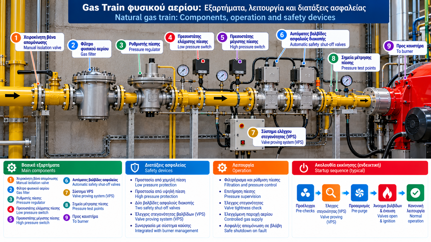
Natural Gas Train: Components, Operation and Safety Devices
A natural gas train is one of the most important subsystems in an industrial gas-fired combustion installation. It prepares, controls and safely supplies gaseous fuel to the burner.
Gas trains are used in industrial boilers, steam generators, furnaces, dryers and other process heating applications.
A properly designed gas train provides more than the required pressure and flow. It also supports safe fuel isolation, pressure supervision and controlled burner startup.
1. What Is a Gas Train?
A gas train is an assembly of components installed in the gas supply line serving a burner.
Depending on the application, it may include:
Manual isolation valve.
Gas filter.
Gas pressure regulator.
Low gas pressure switch.
High gas pressure switch.
Automatic safety shut-off valves.
Valve Proving System (VPS).
Pressure measurement points.
Associated control and safety equipment.
The exact arrangement depends on burner capacity, operating pressure, application requirements and the safety system design.
Not every gas train contains the same components or uses the same component sequence.
2. What Are the Main Functions of a Gas Train?
A gas train performs three primary functions.
Fuel conditioning: It helps remove particles and establish suitable pressure conditions.
Fuel supply control: It enables controlled gas delivery to the burner according to the approved operating logic.
Safe isolation: It interrupts fuel supply when required by the burner management system or protective functions.
Safety depends on the complete assembly and its control architecture, not on one individual valve.
3. Manual Isolation Valve
The manual isolation valve allows the gas line to be isolated during approved procedures.
It must be suitable for natural gas, operating pressure and installation conditions.
Its location is determined by engineering design and accessibility requirements.
A manual valve does not replace the burner’s automatic safety shut-off devices.
4. Natural Gas Filter
The gas filter retains solid particles that may be carried by the fuel.
It protects downstream equipment such as regulators and valves from contamination.
As dirt accumulates, pressure drop across the filter may increase.
The differential pressure is:
ΔP = Pupstream − Pdownstream
This value must be evaluated against actual gas flow and manufacturer performance data.
There is no universal allowable differential pressure for every gas filter.
5. Gas Pressure Regulator
The regulator controls downstream gas pressure to meet burner requirements.
A gas train may receive gas at a higher pressure than the burner needs.
Regulator selection considers:
Minimum and maximum inlet pressure.
Required outlet pressure.
Gas flow.
Response to load changes.
Accuracy and safety requirements.
The reduction in outlet pressure as flow increases is commonly called pressure droop.
It must be assessed using the performance curves of the selected regulator.
6. Low Gas Pressure Switch
A low gas pressure switch supervises whether pressure remains above a specified threshold.
If pressure becomes insufficient, the device may prevent startup or initiate a safe shutdown through the control system.
The exact response depends on burner design.
The pressure switch must not be arbitrarily adjusted to bypass a low-pressure problem.
7. High Gas Pressure Switch
A high gas pressure switch monitors excessive gas pressure.
It may initiate a protective shutdown if pressure exceeds a defined limit.
Its requirement, location and setting depend on the application and risk assessment.
A pressure switch should not be confused with a pressure regulator or an independent overpressure protection device.
8. Automatic Safety Shut-Off Valves
Automatic safety shut-off valves are essential combustion safety components.
Many gas train arrangements use two automatic shut-off valves in series.
They are controlled by the burner management system.
When a protective shutdown occurs or the required control energy is lost, suitably selected valves move to their designated safe state.
The exact arrangement and performance requirements depend on applicable standards and the installation.
9. What Is a Valve Proving System?
A Valve Proving System checks the tightness of automatic shut-off valves where required by the design.
A VPS may evaluate pressure behavior in the volume between two valves.
The specific proving sequence depends on the system technology and approved control logic.
If the test fails, startup may be inhibited and a fault indication generated.
A VPS does not replace gas tightness testing of the entire installation.
10. Gas Pressure Measurement Points
Suitable pressure test points help assess gas train performance.
Depending on the arrangement, measurement points may be provided:
Upstream and downstream of the filter.
Upstream and downstream of the regulator.
At the automatic valve inlet.
At a designated point near the burner.
Measurements must be performed by qualified personnel using appropriate instruments.
Comparing pressure readings under load is particularly useful when diagnosing flow restrictions.
11. How Does a Gas Train Operate During Startup?
The startup sequence is governed by the Burner Management System (BMS) and the installation’s safety requirements.
An illustrative sequence may include:
Burner start request.
Verification of required safety conditions.
Valve proving, where required and according to the approved sequence.
Combustion chamber pre-purge, where applicable.
Transition to ignition position.
Controlled fuel admission and ignition.
Flame confirmation.
Transition to normal operation.
Continuous supervision of critical parameters.
The exact order varies between certified systems.
For example, valve proving may occur at different stages depending on the approved design.
12. What Happens When a Fault Occurs?
When a critical protective function is activated, the BMS performs the required safety action.
Depending on the event, this may involve:
Start inhibition.
Safe shutdown.
Closure of automatic gas valves.
Protective lockout.
Alarm generation.
The response is determined by the approved safety logic and manufacturer requirements.
Repeatedly resetting faults without identifying the cause is not appropriate.
13. How Is Gas Train Size Selected?
Nominal connection diameter alone is not sufficient for selecting a gas train.
Engineers must consider:
Maximum required gas flow.
Minimum and maximum supply pressure.
Required burner inlet pressure.
Pressure losses across each component.
Regulator characteristics.
Valve flow capacity.
Safety requirements.
A gas train with an apparently suitable nominal diameter may still be inadequate if total pressure losses are excessive.
14. Gas Train Sizing Example
Consider a hypothetical industrial burner with a thermal fuel input of 1,000 kW.
Assuming a natural gas lower heating value of 10 kWh/Nm³:
Q = 1,000 / 10 = 100 Nm³/h
This is an initial fuel flow estimate under the stated assumptions.
Actual selection must account for reference conditions, available supply pressure, component pressure losses and burner requirements.
A gas train cannot be selected reliably from the 100 Nm³/h figure alone.
15. Gas Train and Burner Automation
The gas train communicates with the BMS through electrical signals and control commands.
Depending on the design, the system may monitor:
Pressure switch status.
Valve commands and feedback, where provided.
VPS status.
Flame confirmation.
Startup sequence.
Protective trips.
Industrial installations may also transmit these signals to SCADA for monitoring and event recording.
SCADA does not replace required independent combustion safety functions.
16. Common Gas Train Problems
Symptom | Possible Cause | Assessment |
Burner fails to start | Safety prerequisite not satisfied | Review BMS indications |
Low burner gas pressure | Supply or flow restriction | Measure pressure under load |
VPS failure | Unacceptable pressure behavior or system fault | Qualified technician inspection |
Unstable outlet pressure | Regulator behavior or supply variation | Review regulator performance |
High-load shutdowns | Insufficient supply capacity | Assess total pressure losses |
Valve fault | Electrical, mechanical or operational issue | Manufacturer-based inspection |
These are diagnostic possibilities rather than definitive fault identifications.
17. Maintenance and Safety Checks
Gas train maintenance must follow manufacturer instructions and installation requirements.
It may include:
Inspection of components and connections.
Required tightness checks.
Filter condition assessment.
Regulator operation checks.
Pressure switch testing.
Automatic valve checks.
VPS testing, where installed.
Verification of safety interlocks.
Documentation of results.
Tests must be carried out by qualified personnel using approved procedures.
Pressure switches, valves and other protective devices must never be bypassed to keep a burner running.
18. Relevant Technical Standards
Depending on the application, relevant references include:
EN 676: Automatic forced draught burners for gaseous fuels.
EN 88-1: Pressure regulators and associated safety devices for gas appliances, within the standard’s scope.
EN 161: Automatic shut-off valves for gas burners and appliances.
EN 1643: Valve proving systems for automatic shut-off valves.
EN 1854: Pressure sensing devices for gas burners and appliances.
EN 15001-1: Design and construction of gas installations within its scope.
Applicability must be verified according to the equipment, installation category and regulatory framework.
Conclusion
A natural gas train is a critical part of industrial gas burner safety.
The filter protects downstream components, the regulator controls pressure, pressure switches supervise specified limits and automatic shut-off valves provide the required fuel isolation.
Correct selection, integration with the BMS and planned maintenance are essential for reliable operation.
Engineering design, adjustment, testing and intervention must be performed by qualified personnel.