
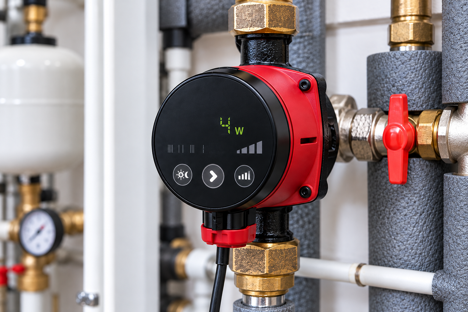
How to Choose a Heating Circulation Pump: Flow Rate, Pump Head and Correct Sizing
Selecting a heating circulation pump involves more than matching the size or model number of an existing pump. Correct sizing requires understanding the water flow rate needed to transfer heat and the pump head required to overcome hydraulic resistance.
An undersized pump may fail to deliver adequate circulation. An oversized pump may create excessive differential pressure, unwanted noise and unnecessary electricity consumption.
This guide explains how to size a heating circulator, calculate the required duty point and evaluate different heating applications.
1. Information Required Before Selecting a Pump
Before selecting a circulation pump, determine:
The thermal output required by the circuit, in kW.
The design supply and return temperatures.
The heating system type.
Pipe lengths, internal diameters and layout.
Pressure losses through valves, filters and heat exchangers.
Whether thermostatic valves or other flow controls are installed.
The heat source manufacturer’s hydraulic requirements.
The circulating fluid and operating temperature range.
The rated output of the boiler does not necessarily equal the heat transfer requirement of every individual circuit. Zoned installations may require separate hydraulic calculations.
2. Calculating the Required Water Flow Rate
The required flow rate depends on the heat transferred and the temperature difference between supply and return.
For water under typical heating conditions:
Q = P / (1.163 × ΔT)
Where:
Q = Flow rate in m³/h.
P = Thermal power in kW.
ΔT = Supply-to-return temperature difference in °C.
1.163 = Approximate conversion factor for water.
The coefficient varies with fluid properties and temperature. Water-glycol mixtures require calculations based on their actual thermophysical properties.
Example 1: Radiator Heating Circuit
Assume:
Heating capacity: 18 kW.
Design temperature difference: 20°C.
Q = 18 / (1.163 × 20)
Q ≈ 0.77 m³/h
The design flow rate is approximately 0.77 m³/h.
Example 2: Smaller Temperature Difference
For the same 18 kW heating load but a 10°C temperature difference:
Q = 18 / (1.163 × 10)
Q ≈ 1.55 m³/h
Halving the temperature difference approximately doubles the required water flow rate.
This helps explain why some low-temperature heating systems require higher flow rates than traditional radiator installations.
3. Understanding Required Pump Head
Pump head represents the energy added to the liquid per unit weight and is commonly expressed in metres.
In a completely filled and properly vented closed heating circuit, the building’s vertical height is not simply added to the circulation pump’s required head.
Instead, the pump primarily overcomes pressure losses caused by water moving through the system.
These losses include:
Pipe friction.
Elbows and fittings.
Control and balancing valves.
Filters and strainers.
Heat exchangers.
Manifolds and distribution circuits.
For water, approximately:
1 metre of water column ≈ 9.81 kPa
Example
If the total pressure loss through the hydraulically most demanding circuit is 35 kPa:
H = 35 / 9.81
H ≈ 3.57 m
The pump must deliver the required flow at approximately 3.57 metres of head.
A maximum pump head rating of 3.6 metres alone does not demonstrate suitability.
4. How Are Hydraulic Pressure Losses Calculated?
Pressure losses can be divided into pipe friction losses and local component losses.
Pipe Friction Losses
These depend on pipe length, internal diameter, flow velocity, surface roughness and fluid properties.
A commonly used engineering equation is Darcy–Weisbach:
Δp = f × (L/D) × (ρv²/2)
Where:
Δp = Pressure loss in Pa.
f = Darcy friction factor.
L = Pipe length in metres.
D = Internal pipe diameter in metres.
ρ = Fluid density in kg/m³.
v = Average flow velocity in m/s.
Local Losses
Local losses occur through elbows, tees, valves, reducers and other fittings.
They can be estimated using appropriate loss coefficients or manufacturer performance data.
For heat exchangers and control valves, manufacturer pressure-drop curves should be used whenever available.
5. Which Circuit Determines the Required Pump Head?
In a heating system with several parallel branches, pressure losses are not calculated by adding every branch as though they were connected in series.
The pump must provide the total required flow while overcoming the pressure losses along the hydraulically most demanding path, including common pipe sections.
Hydraulic balancing and valve operating conditions must also be considered.
Complex networks require detailed hydraulic calculations.
6. How to Read a Circulation Pump Performance Curve
A pump performance curve shows the relationship between flow rate and pump head.
Typically:
The horizontal axis represents flow rate Q.
The vertical axis represents pump head H.
The actual operating point is determined by the intersection of the pump curve and the system resistance curve.
This is known as the duty point or operating point.
Example
Suppose the calculated requirements are:
Flow rate: 1.2 m³/h.
Pump head: 3.5 m.
The pump must be capable of operating at:
Q = 1.2 m³/h and H = 3.5 m
A pump advertised with a maximum head of 4 metres may not meet this requirement, because maximum head is generally achieved at zero or very low flow.
Always check the manufacturer’s actual performance curves.
7. Selecting a Pump for Radiator Heating
Radiator circuits must be sized according to the heating load and design temperature difference.
Where thermostatic radiator valves are installed, flow demand changes as valves open and close.
A modern electronic circulator operating in an appropriate proportional differential pressure mode can respond to these changing hydraulic conditions.
However, the correct control mode depends on the installation and manufacturer guidance.
8. Selecting a Pump for Underfloor Heating
Underfloor heating systems often use smaller design temperature differences than traditional high-temperature radiator circuits.
For the same thermal power, this can increase the required flow rate.
At the same time, underfloor heating loops create hydraulic resistance that depends on their lengths, diameters and individual flow rates.
Important design considerations include:
Required flow through each loop.
Pressure loss along the most demanding loop.
Manifold and valve resistance.
Mixing unit characteristics, where installed.
Zone actuators and system controls.
Constant differential pressure operation can be suitable for certain underfloor heating arrangements, but it is not a universal requirement.
9. Selecting a Pump for a Heat Pump System
Heat pumps have specific hydraulic operating requirements.
Insufficient water flow can cause operating faults, reduced performance or defrost-related problems, depending on the equipment.
Check:
Minimum and nominal flow requirements.
Heat exchanger pressure loss.
External distribution network resistance.
Hydraulic separators or buffer tanks.
Whether the heat pump already includes a circulator.
Antifreeze solution properties, where applicable.
In some installations, the integrated pump is sufficient. Others require a secondary circulator in a separate hydraulic circuit.
A second pump should not be added without reviewing the hydraulic arrangement.
10. What Do 25-40, 25-60 and 25-80 Mean?
In many circulator product ranges, these designations indicate a nominal connection size and an approximate maximum head.
Designation | Common interpretation |
25-40 | Nominal connection size 25; maximum head approximately 4 m |
25-60 | Nominal connection size 25; maximum head approximately 6 m |
25-80 | Nominal connection size 25; maximum head approximately 8 m |
The exact designation depends on the manufacturer and product series.
These numbers do not specify the available flow rate at every pump head.
Installation length, connection geometry and electrical specifications must also be verified.
11. Complete Pump Sizing Example
Consider a hypothetical radiator heating circuit.
Design Data
Thermal power: 24 kW.
Design temperature difference: 15°C.
Pressure loss along the most demanding circuit: 38 kPa.
Circulating fluid: water.
Step 1: Calculate Flow Rate
Q = 24 / (1.163 × 15)
Q ≈ 1.38 m³/h
Step 2: Calculate Pump Head
H = 38 / 9.81
H ≈ 3.87 m
Step 3: Establish the Duty Point
The required design point is approximately:
Flow rate: 1.38 m³/h
Pump head: 3.87 m
Step 4: Review Pump Curves
Select a circulator capable of operating at this point under an appropriate control setting.
Check its efficiency and available operating range.
Step 5: Verify Compatibility
Confirm:
Installation dimensions.
Hydraulic connections.
Maximum operating temperature and pressure.
Fluid compatibility.
Electrical supply.
Control system compatibility.
This example does not identify or recommend a particular commercial model.
12. Common Pump Sizing Mistakes
Sizing by boiler capacity alone: This ignores design temperature difference and hydraulic resistance.
Sizing by building height: In a properly filled closed heating system, building height is not equivalent to the required circulation head.
Selecting by maximum head alone: Maximum head does not indicate performance at the required flow rate.
Automatically choosing a larger pump: Oversizing can cause noise, excessive pressure and wasted electricity.
Ignoring hydraulic balancing: A correctly sized pump cannot necessarily compensate for poor distribution network balancing.
Ignoring heat pump manufacturer requirements: Incorrect flow can result in operating conditions outside the equipment’s specified limits.
13. Frequently Asked Questions
How Do I Know Which Heating Circulation Pump I Need?
Determine the required design flow rate, pump head at that flow rate, connection dimensions and control requirements.
Is a 25-80 Pump Better Than a 25-60?
Not necessarily. The correct choice is the pump that meets the required duty point efficiently and operates appropriately within the system.
Can I Calculate Pump Head Using Floor Area Alone?
No. Floor area does not provide sufficient information about the hydraulic resistance of the heating network.
Does Underfloor Heating Require a Different Circulation Pump?
Selection depends on required flow, circuit pressure losses and control arrangements, rather than the heating system label alone.
Should I Choose a Pump With Much Higher Head as a Safety Margin?
An arbitrary large margin is not recommended. Sizing should be based on documented hydraulic requirements and verified performance curves.
Conclusion
Correct heating circulation pump selection is based on two fundamental parameters: required water flow rate and pump head at the design duty point.
Heating capacity and design temperature difference determine flow rate, while the hydraulic resistance of the distribution network determines required head.
Final selection should be verified using the manufacturer’s official performance curves and installation requirements.
The calculations in this guide are educational examples and do not replace a professional hydraulic design or manufacturer instructions.
Technical References
Grundfos — Pump sizing, selection tools and technical documentation: https://www.grundfos.com
Wilo — Circulator selection and technical information: https://wilo.com
ASHRAE — HVAC engineering reference publications: https://www.ashrae.org
European Union — Regulation (EC) No 641/2009 on ecodesign requirements for circulators: https://eur-lex.europa.eu/eli/reg/2009/641/oj