
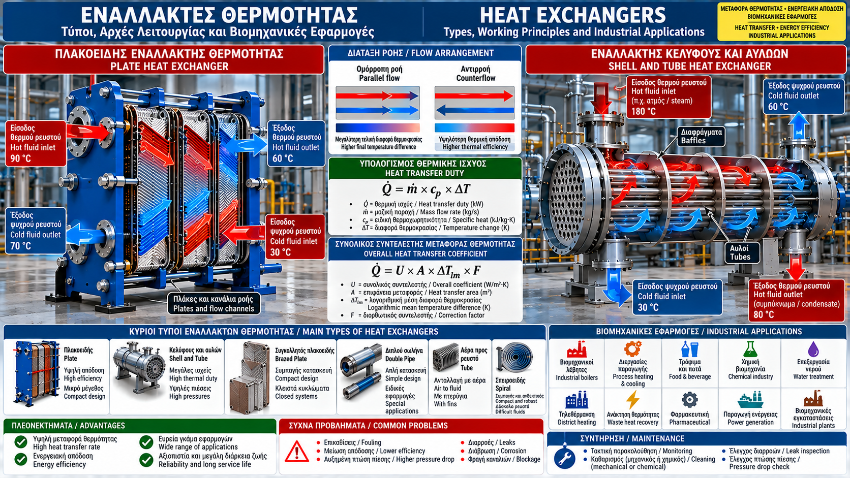
# Heat Exchangers: Types, Working Principles and Industrial Applications
## Introduction
Heat exchangers are essential components of modern industrial systems. Their purpose is to transfer thermal energy between two or more fluid streams, enabling process heating, cooling, waste heat recovery and improved energy efficiency.
They are widely used in steam boiler systems, hot-water networks, food processing plants, chemical facilities, water treatment installations and energy production.
Correct heat exchanger selection requires a detailed understanding of operating temperatures, thermal duty, flow rates, allowable pressure drop and fluid properties.
## 1. What Is a Heat Exchanger?
A heat exchanger is a device that transfers heat from a hotter fluid to a colder fluid.
In most industrial designs, the fluids are separated by a solid heat transfer surface, preventing direct mixing.
Heat moves by convection from the hot fluid to the wall, conduction through the wall and convection from the wall to the colder fluid.
Direct-contact heat exchangers also exist, but they are intended for applications where contact between the fluids is acceptable.
## 2. Basic Working Principle
Heat transfer occurs because of a temperature difference between the two streams.
For example, hot water entering at 90 °C may transfer heat to a separate water circuit entering at 30 °C.
The hot stream loses energy while the cold stream gains energy.
The outlet temperatures depend on flow rates, heat capacities, heat transfer area and flow configuration.
## 3. Heat Transfer Mechanisms
Three mechanisms are relevant:
Conduction: heat transfer through the separating metal wall.
Convection: heat transfer between the moving fluid and the heat transfer surface.
Radiation: energy transfer by electromagnetic waves. Radiation becomes particularly important at high temperatures but is usually not the dominant mechanism in conventional liquid-to-liquid heat exchangers.
## 4. Main Types of Heat Exchangers
Common industrial configurations include:
• Plate heat exchangers.
• Shell-and-tube heat exchangers.
• Brazed plate heat exchangers.
• Double-pipe heat exchangers.
• Finned-tube air-to-fluid exchangers.
• Spiral heat exchangers.
• Specialized flue-gas heat recovery exchangers.
Each configuration offers a different balance of thermal performance, mechanical strength, maintainability and capital cost.
## 5. Plate Heat Exchangers
Plate heat exchangers use thin metal plates arranged to form alternating flow channels.
Hot and cold fluids pass through adjacent channels, transferring heat through the plate surfaces.
Advantages include:
• High heat transfer performance per unit volume.
• Compact installation footprint.
• Expandability in certain gasketed designs.
• Access for mechanical cleaning in serviceable models.
Limitations include:
• Potential blockage in narrow channels.
• Temperature and pressure limitations depending on the design and gasket materials.
• Possible internal leakage following plate or sealing failure.
## 6. Shell-and-Tube Heat Exchangers
Shell-and-tube exchangers contain a bundle of tubes enclosed within a cylindrical shell.
One fluid flows through the tubes while the other flows on the shell side.
These exchangers are widely used for large thermal duties, high-pressure services, steam condensation and demanding industrial applications.
Their construction may include multiple tube passes, internal baffles and different tube arrangements.
## 7. Brazed Plate Heat Exchangers
Brazed plate exchangers are manufactured using thin plates joined by a brazing process, often with copper or nickel depending on the application.
They provide a compact, sealed design suitable for compatible closed-loop water systems and other industrial services.
They cannot be disassembled for mechanical cleaning.
Their suitability depends on fluid chemistry, water quality, material compatibility and the manufacturer's operating limits.
## 8. Parallel Flow and Counterflow
In parallel-flow arrangements, both fluids enter from the same end and travel in the same direction.
In counterflow arrangements, the fluids travel in opposite directions.
Counterflow frequently provides higher thermal effectiveness for the same transfer area because it maintains a more favorable temperature difference along the exchanger.
Actual performance depends on geometry, number of passes and the heat capacity rates of the streams.
## 9. Calculating Heat Transfer Duty
For a single-phase fluid with approximately constant heat capacity, the heat transfer rate is:
Q̇ = ṁ × cp × ΔT
Where:
Q̇ = heat transfer duty (kW).
ṁ = mass flow rate (kg/s).
cp = specific heat capacity (kJ/kg·K).
ΔT = fluid temperature change (K).
This equation is useful for assessing actual heat exchanger performance using field measurements.
## 10. Practical Thermal Duty Example
Consider a water circuit operating with:
Flow rate: 10 m³/h.
Inlet temperature: 80 °C.
Outlet temperature: 60 °C.
Using an approximate water density of 1,000 kg/m³ and cp ≈ 4.18 kJ/kg·K, the mass flow rate is approximately 2.78 kg/s.
Therefore:
Q̇ ≈ 2.78 × 4.18 × 20 = 232 kW.
The exchanger transfers approximately 232 kW from this stream under steady operating conditions, assuming relatively small external heat losses.
Using water properties at the actual operating temperatures provides a more precise result.
## 11. Overall Heat Transfer Coefficient
Heat exchanger performance is strongly influenced by the overall heat transfer coefficient, U.
A common design relationship is:
Q̇ = U × A × ΔTlm × F
Where:
U = overall heat transfer coefficient.
A = effective heat transfer area.
ΔTlm = logarithmic mean temperature difference.
F = correction factor for applicable flow arrangements, when required.
The overall coefficient depends on fluid properties, flow conditions, wall material and fouling resistance.
## 12. The Importance of Flow Rate
Flow rate determines how much thermal energy each stream can transport.
Insufficient flow can reduce total heat transfer duty even when the measured temperature difference appears large.
Increasing flow may improve convective heat transfer, but it generally increases pressure drop and pumping energy consumption.
Selection must consider both thermal and hydraulic performance.
## 13. Pressure Drop
Every heat exchanger introduces hydraulic resistance.
Pressure drop depends on flow rate, viscosity, channel geometry and fouling conditions.
An abnormal increase may indicate:
• Blocked channels.
• Fouling deposits.
• Inadequate filtration.
• Operation outside the intended flow range.
• Changes in fluid properties.
Pressure drop should be evaluated separately on the hot and cold sides.
## 14. Fouling and Deposits
Fouling is one of the most common causes of reduced heat exchanger performance.
Typical sources include:
• Hardness scale.
• Iron oxides and corrosion products.
• Biological growth.
• Suspended solids.
• Organic residues.
Deposits add thermal resistance and may increase pressure drop, reducing performance and increasing operating costs.
## 15. Material Selection
Construction materials must be compatible with operating temperature, pressure, fluid chemistry and corrosion exposure.
Common choices include:
• Stainless steel 316L.
• Carbon steel for suitable services.
• Nickel alloys for demanding conditions.
• Titanium for selected corrosion-resistant applications.
Material suitability depends not only on alloy designation but also on chloride concentration, temperature and actual service conditions.
## 16. Heat Exchangers in Steam Systems
Steam is frequently used as a heating medium because it releases substantial latent heat during condensation.
In a steam-to-water exchanger, steam condenses on the heating side while water gains heat on the opposite side.
Stable operation requires effective condensate drainage, removal of non-condensable gases where necessary, pressure control and appropriate protective devices.
Condensate accumulation may reduce heat transfer and contribute to problems such as water hammer.
## 17. Waste Heat Recovery
Heat exchangers can recover thermal energy that would otherwise be discharged to the environment.
Applications include:
• Feedwater preheating using hot process streams.
• Condensate heat recovery.
• Flue-gas heat recovery using suitable economizers.
• Preheating production streams.
Potential energy savings should be evaluated using actual operating hours, available heat duty and required process temperatures.
## 18. Industrial Applications
Heat exchangers are used in:
• Industrial boiler and steam generation systems.
• Process-water heating.
• Food and beverage production.
• Pharmaceutical and chemical manufacturing.
• Water treatment facilities.
• District heating networks.
• Thermal energy recovery systems.
The preferred configuration depends on heat duty, fluid cleanliness, operating conditions and maintenance requirements.
## 19. Instrumentation and Performance Monitoring
Useful field measurements include:
• Hot-side inlet and outlet temperatures.
• Cold-side inlet and outlet temperatures.
• Flow rate of each circuit.
• Inlet and outlet pressures on each side.
• Filter and control-valve conditions.
These measurements support thermal duty calculations, heat balance checks and detection of deteriorating performance.
## 20. Selecting the Correct Heat Exchanger
Selection should be based on:
1. Required thermal duty.
2. Inlet temperatures and target outlet temperatures.
3. Flow rates and fluid properties.
4. Design pressures and allowable pressure drops.
5. Fluid quality and corrosiveness.
6. Cleaning and maintenance requirements.
7. Applicable safety and construction standards.
Selecting a heat exchanger only by nominal power rating, without temperature and hydraulic data, may result in poor performance.
## 21. Common Operating Problems
Frequent issues include:
• Reduced heat transfer.
• Excessive pressure drop.
• Internal or external leakage.
• Plate or tube corrosion.
• Channel blockage.
• Inadequate condensate drainage.
• Incorrect control-valve operation.
Troubleshooting should rely on measured operating data rather than outlet temperature alone.
## 22. Maintenance and Safe Operation
Preventive maintenance includes monitoring temperatures, flow rates and pressure drop, checking for leaks, cleaning filters and scheduling inspections.
Cleaning may be mechanical or chemical depending on exchanger construction and the nature of deposits.
Before maintenance, equipment must be safely isolated, depressurized, cooled and drained according to the applicable work procedures.
Cleaning chemicals must be compatible with the construction materials, seals and manufacturer instructions.
## 23. Conclusion
Heat exchangers are critical to energy efficiency and reliability in industrial facilities.
Understanding heat transfer mechanisms, flow arrangements, thermal duty and hydraulic behavior supports correct selection and operation.
Systematic performance monitoring and appropriate maintenance help reduce failures, limit energy losses and extend equipment service life.
Thermosphere.gr — Technical knowledge for industry, heating and energy efficiency.